Coupled Mass-Spring Systems and Imaging Methods for Scanning Probe Microscopy

a mass spring system and scanning probe technology, applied in the field of cantilevers and imaging methods for use in atomic force microscopy, can solve the problem that the scanning probe microscope is not sufficient to probe the pre-processed material, and achieve the effect of improving the capability of scanning probe microscopes, higher versatility, and high performan

Inactive Publication Date: 2010-10-07
RGT UNIV OF CALIFORNIA
View PDF44 Cites 11 Cited by
  • Summary
  • Abstract
  • Description
  • Claims
  • Application Information

AI Technical Summary

Benefits of technology

[0006]This invention improves the capability of scanning probe microscopes by using a separate second sensor resonator to preamplify higher harmonics occurring at periodic indentation of sample materials. This separation leads to a higher performance and higher versatility of the scanning probe microscope over a wide range of different sample materials. Also aspects of on-chip sensing become practical with this invention.
[0007]The main embodiment of this invention consists of two coupled micromechanical mass-spring systems, consisting of two cantilever arms with one fixed and one free end each. These two cantilever arms are connected to each other for energy transfer. One of these cantilever arms is called the actuator cantilever, the other one the sensor cantilever. A probe tip projects from the free end of the actuator cantilever. This system allows the amplification of a desired higher harmonic frequency and a suppression of the excitation frequency.
[0012]Another embodiment of this invention consists of an actuation cantilever with a second mass-spring indentation cantilever. In this embodiment the functions of actuation and indentation are separated. The actuation force is applied on the actuation cantilever, and the probe tip projects from the other side of the indentation cantilever. In one embodiment one or more sensor cantilevers are directly attached to the indentation cantilever, in another embodiment the sensor cantilevers have one fixed end and one free end and are coupled to the probe tip side of the indentation cantilever. In this embodiment, the indentation cantilever has a much higher resonant frequency than all other cantilevers in this embodiment, therefore allowing a trajectory change due to the nonlinear indentation of the probe tip into the sample surface. In a variation of this embodiment, a single actuation cantilever is used for more than one indentation mass-spring system. With this single actuation cantilever, an easy synchronization of an array of sensors can be achieved.
[0017]In still another specific embodiment, the sensor cantilever is comprised of a piezoresistive material, giving it the ability to monitor the movement of the sensor cantilever directly on the chip with the same advantages as the embodiment with the piezoelectric sensor cantilever.

Problems solved by technology

Therefore it is not sufficient to merely probe the pre-processed material in a spot and assume that the material properties will be constant over the sample.

Method used


Image

  • Coupled Mass-Spring Systems and Imaging Methods for Scanning Probe Microscopy
  • Coupled Mass-Spring Systems and Imaging Methods for Scanning Probe Microscopy
  • Coupled Mass-Spring Systems and Imaging Methods for Scanning Probe Microscopy

Examples


Embodiment Construction

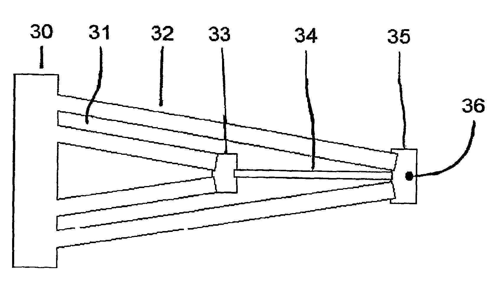
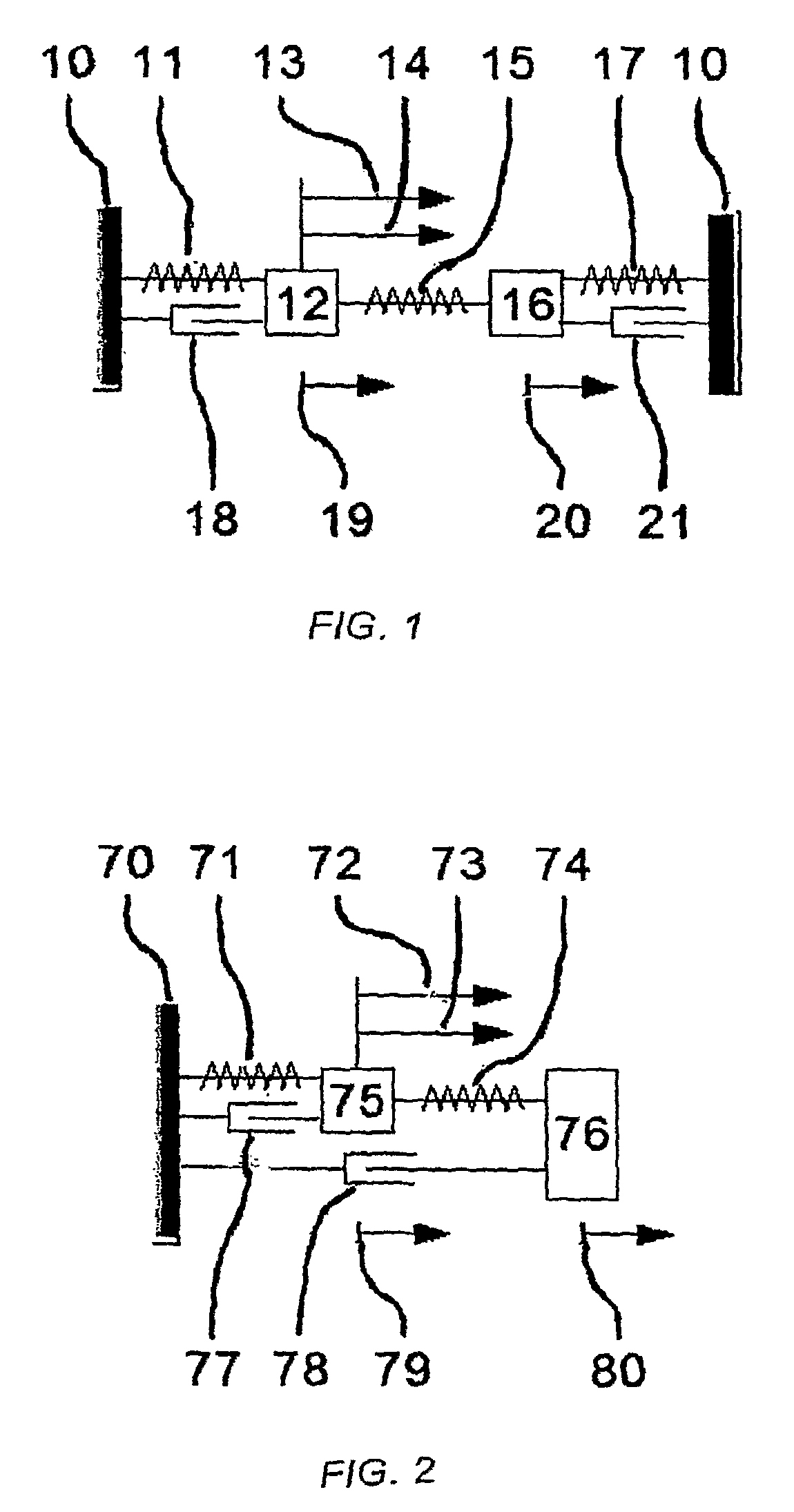
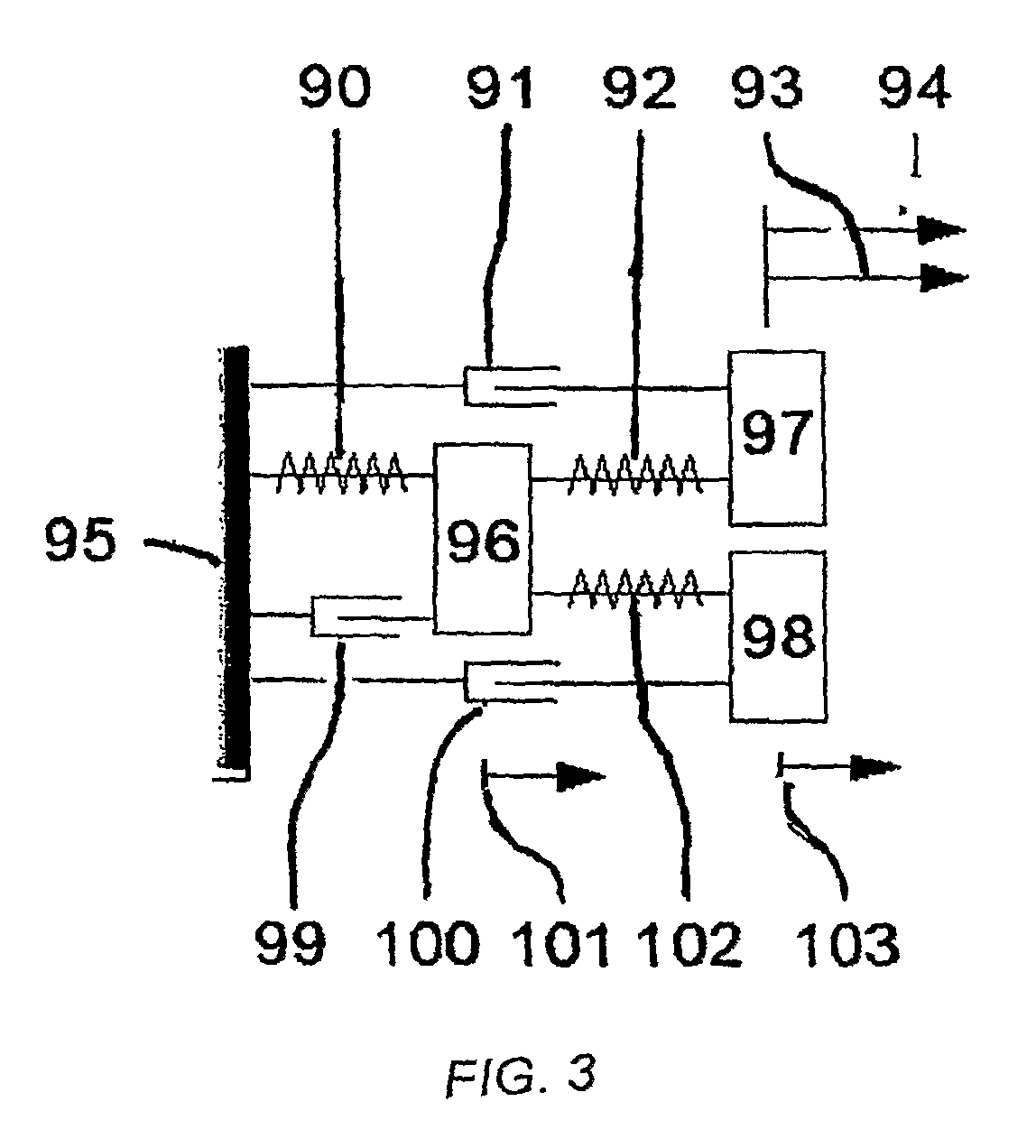
[0034]The invention provides a coupled mass-spring system for use as a scanning probe microscope, and method of using it. In general terms, the system comprises one or more oscillators including an actuator oscillator, a probe on one of the oscillators for contacting a sample, and a sensor oscillator spaced from the probe-bearing oscillator and coupled to the probe-bearing oscillator for transfer of energy between the sensor oscillator and the probe-bearing oscillator. This arrangement of components enables mechanical amplification of a desired frequency in the sensor oscillator to improve the sensitivity and measurement range of the scanning probe microscope. In an embodiment of the invention, the probe-bearing oscillator is an indentation oscillator. In another embodiment of the invention, the probe-bearing oscillator is the actuator, which serves as an actuator / indentation oscillator.

[0035]The sensor oscillator and the probe-bearing oscillator can be coupled by any appropriate ar...


PUM


Abstract

A novel way for constructing and operating scanning probe microscopes to dynamically measure material properties of samples, mainly their surface hardness, by separating the functions of actuation, indentation and sensing into separate dynamic components. The amplitude and phase shift of higher modes occurring at periodic indentations with the sample are characteristic values for different sample materials. A separate sensor cantilever, connected to the indentation probe tip, has the advantage of a high mechanical amplification of a desired higher mode while suppressing the actuation signal itself. The operational range of the sensor can be extended just by switching the actuation signal to another submultiple of the sensor cantilever's resonance frequency and / or by using more than one sensor cantilever for each indentation tip.

Description

CROSS-REFERENCE TO RELATED APPLICATIONS[0001]This application claims the benefit of Provisional Patent Application No. 60 / 773,179, filed Feb. 14, 2006FIELD OF THE INVENTION[0002]The invention relates to cantilevers and imaging methods for use in atomic force microscopy and, in particular, to a scanning probe cantilever and imaging methods using the cantilever for imaging at higher harmonic modes of the excitation frequency in tapping mode atomic force microscopy.BACKGROUND OF THE INVENTION[0003]The atomic force microscopy was described for the first time in 1986 by G. Binning et al. [1]. This method, where samples are examined with an atomically sharp tip (typically around 20 nm diameter at the tip) allows atomic resolution for topography measurements and atomic manipulation capability. Together with the topography, more properties of the samples can be extracted [2] with the atomic force microscopy, either statically with the Nanoindenter or dynamically by using the microscope in t...

Claims


Application Information

Patent Timeline
Patent Type & Authority Applications(United States)
IPC IPC(8): G01Q30/00
CPCB82Y35/00G01Q10/045G01Q60/366G01Q60/34G01Q60/38G01Q20/04
Inventor TURNER, KIMBERLY L.ZEYEN, BENEDIKT
Owner RGT UNIV OF CALIFORNIA
Why Eureka
Try Eureka