Engine fuel delivery systems, apparatus and methods

a fuel delivery system and engine technology, applied in the direction of machines/engines, combustion gas purification/modification, domestic heating, etc., can solve the problems that sensors or probes and related hardware and software can be cost prohibitive for some engine applications

Active Publication Date: 2010-10-14
WALBRO LLC
View PDF16 Cites 63 Cited by
  • Summary
  • Abstract
  • Description
  • Claims
  • Application Information

AI Technical Summary

Benefits of technology

[0012]One form of a carburetor includes a carburetor body including an air and fuel mixing passage, a valve rotatably disposed in the mixing passage, and a control module. The control module may be carried on the carburetor body and includes a circuit board and a rotary position sensor carried on the circuit board and cooperating with a portion of the valve to sense rotary position of the valve.
[0013]Another form of a carburetor includes a body including a fuel and air mixing passage, a solenoid associated with the body and with one or more control passages through which fuel or air flow. The solenoid includes a valve that may be opened to permit communication between two or more passages and may be closed to prevent communication between said two or more passages. In one ...

Problems solved by technology

But such sensors or probes and related hardware and software can be cost prohibitive for some engine a...

Method used


Image

  • Engine fuel delivery systems, apparatus and methods
  • Engine fuel delivery systems, apparatus and methods
  • Engine fuel delivery systems, apparatus and methods

Examples


Embodiment Construction

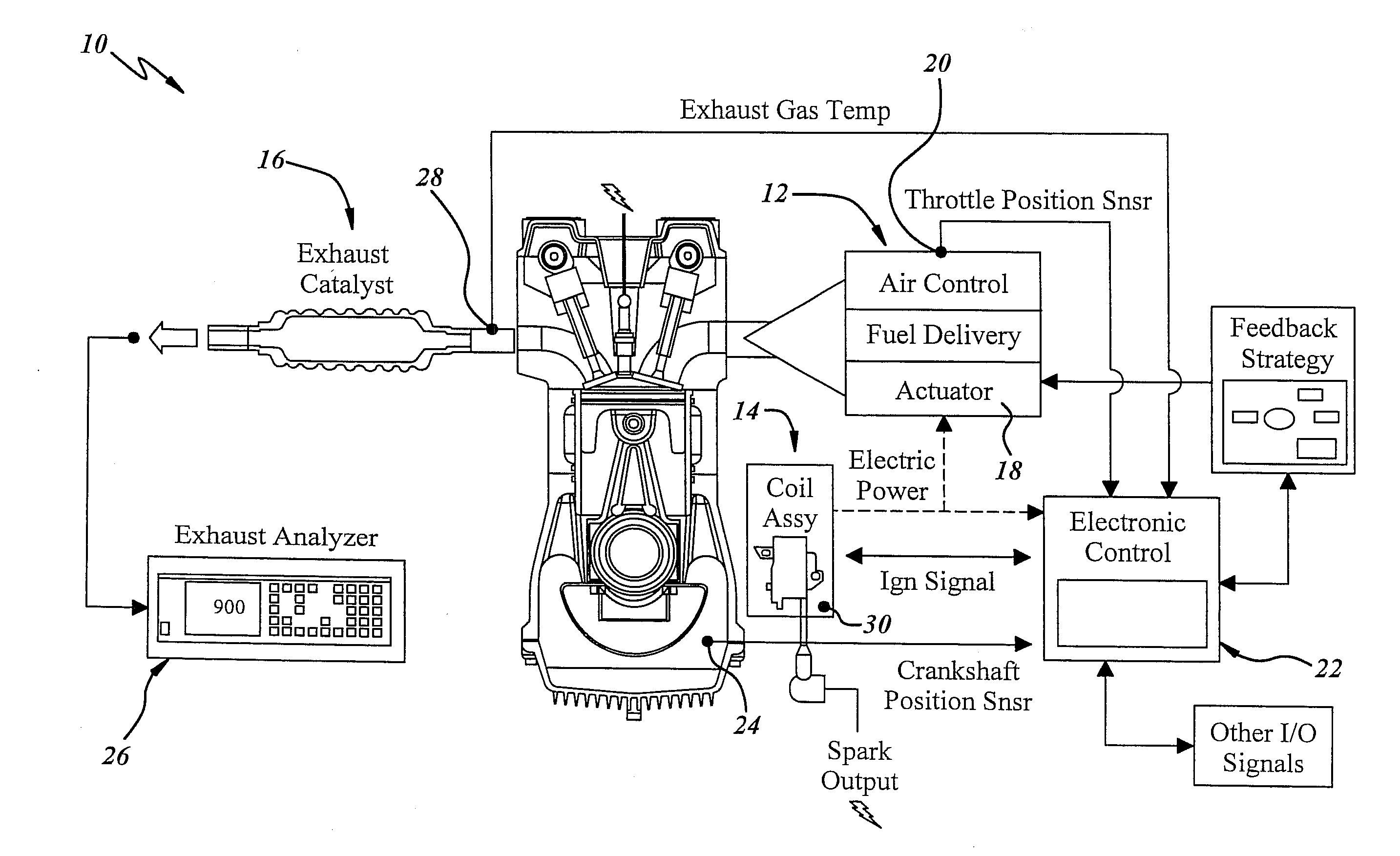
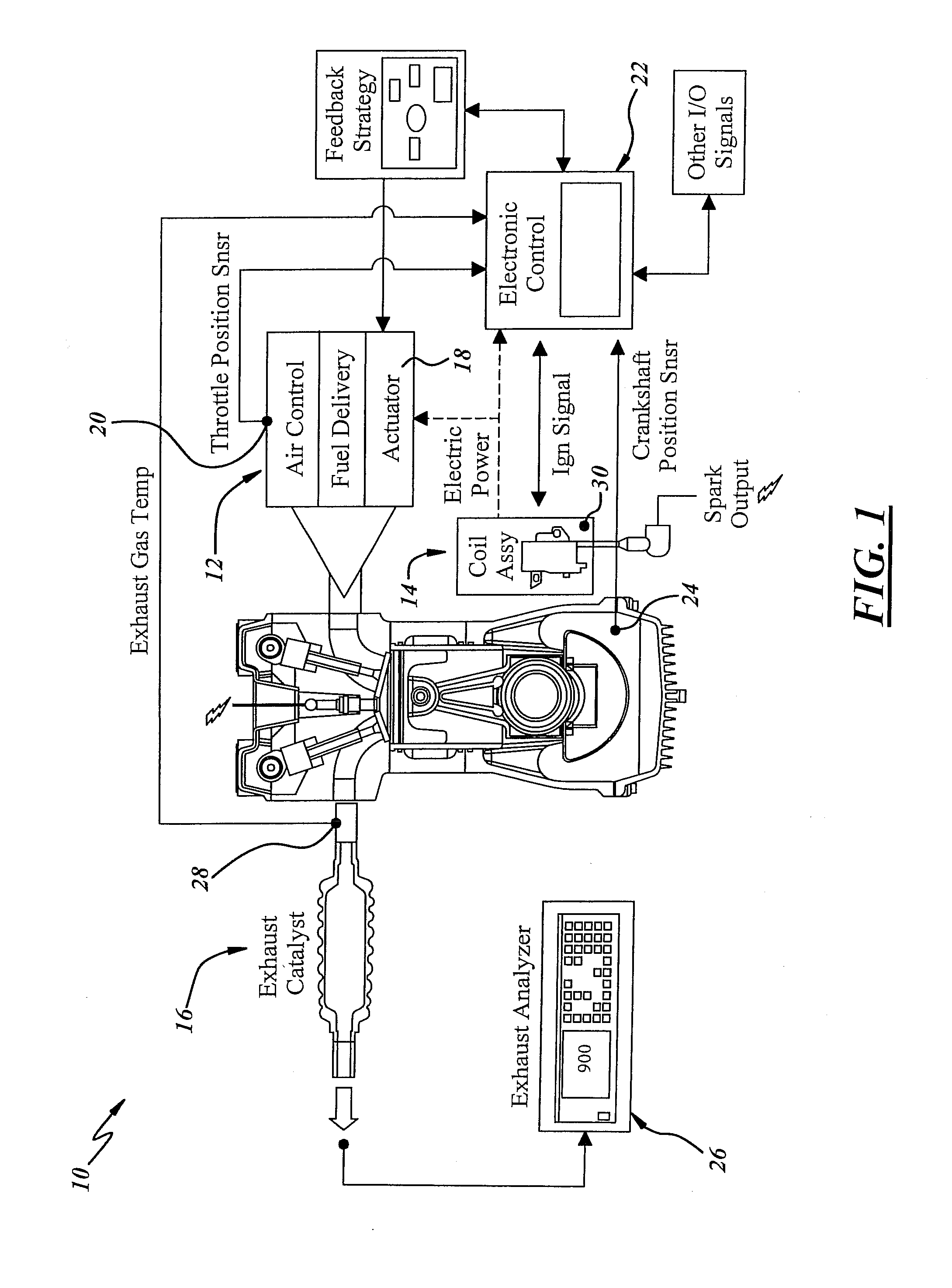
[0066]Referring in more detail to the drawings, FIG. 1 is a schematic of an engine system with an engine 10 that may be operated in accordance with an exemplary method described herein below. The engine 10 may be any suitable two-stroke or four-stroke engine. Such engines may include, for example, single cylinder engines up to about 225 cc displacement such as for walk-behind lawn mowers, or single or multiple cylinder engines greater than about 225 cc displacement such as for riding lawn tractors or similar lawn or garden ground supported equipment. Other applications may include smaller two wheel or all-terrain-vehicle (ATV) engines up to about 150 cc displacement, or even low-cost larger displacement engines for snowmobiles or ATV's.

[0067]Still referring to FIG. 1, the engine 10 may include a carburetor 12 that provides a combustible charge of air and fuel to the engine, a power generation unit (PGU) 14 to produce engine ignition spark to ignite the combustible charge, and prefer...


PUM

PropertyMeasurementUnit
Temperatureaaaaaaaaaa
Pressureaaaaaaaaaa
Magnetic fieldaaaaaaaaaa

Abstract

A method of operating an engine is disclosed, which includes determining a peak power condition for the engine, measuring a temperature associated with the engine at said peak power condition, comparing the temperature measured with a previously determined temperature associated with a known peak power condition of the engine, determining an offset value based on the comparison made in step, controlling at least one of an air-fuel mixture delivered to the engine or ignition spark timing based on said offset value. Various engine fuel delivery systems, carburetors, fuel injection and control systems also are disclosed.

Description

REFERENCE TO CO-PENDING APPLICATIONS[0001]This application claims the benefit of and priority from U.S. Provisional Patent Application Ser. Nos. 61 / 000,451 filed Oct. 27, 2007 and 61 / 094,973 filed Sep. 7, 2008.TECHNICAL FIELD[0002]The present invention relates generally to engine fuel systems and more particularly to fuel systems for combustion engines and methods of operating combustion engines.BACKGROUND[0003]Many small internal combustion engines are supplied with a combustible charge of air and fuel using a carburetor. A typical carburetor includes a body defining a liquid fuel chamber, an air and fuel mixing passage, and one or more fuel passages in communication between the fuel chamber and the air and fuel mixing passage. The fuel passages communicate with the mixing passage between an air inlet at an upstream end and an air and fuel mixture outlet at a downstream end. Typically, a choke valve is disposed in the air and fuel mixing passage near the upstream end to control a q...

Claims


Application Information

Patent Timeline
IPC IPC(8): F02D41/00F02D28/00F02M7/18
CPCF02M17/04F02D2400/06F02D41/1446F02D31/009F02P3/0815F02D35/0053F02D31/006
Inventor ANDERSSON, MARTIN N.BEJCEK, ANDREW E.CASONI, MASSIMOGALKA, WILLIAM E.HEALY, CYRUS M.PASCOLI, ALESSANDROROCHE, RONALD H.SWANSON, MARK S.VAN ALLEN, JAMES E.WOODY, JOHN C.
Owner WALBRO LLC
Why Eureka
Try Eureka