Filter cleaning apparatus and filter cleaning method

a filter and cleaning apparatus technology, applied in the field of filter cleaning apparatus and filter cleaning method, can solve the problems of affecting the cleaning effect, the fine powder stuck in the recesses of the pleat tends to agglomerate, and the processing efficiency of the filter is reduced, so as to achieve efficient cleaning process, efficient cleaning, and efficient use of the energy of the bubbles

Inactive Publication Date: 2010-10-14
FREUNT IND
View PDF3 Cites 10 Cited by
  • Summary
  • Abstract
  • Description
  • Claims
  • Application Information

AI Technical Summary

Benefits of technology

[0016]According to the filter cleaning apparatus of the present invention where the filter is put in the processing container in which the cleaning liquid is reserved and a cleaning process is carried out by rotating the filter by means of the bubble flow or the liquid containing bubbles jetted from the nozzle device attached to the processing container, the filter is so disposed as to be capable of rotating around the rotational axis line that is substantially horizontal, and the nozzle device is disposed below the filter. Therefore, an uplift pressure of bubbles rising out of the liquid into the atmosphere is added to the bubble flow jetted from the nozzle device. As a result of the synergic effect of the jet pressure of the bubble flow and the uplift pressure, the filter rotates in an efficient way, thereby enabling the energy of the bubbles to be used efficiently and making an efficient cleaning process possible.
[0017]According to the filter cleaning method of the present invention by which the filter is put in the pr

Problems solved by technology

However, in such a filter, the clogging of the filter medium hampers the flow of the gas and the fluidization of the powder and granular material, leading to a decrease in processing efficiency.
However, even such a dust-off process cannot dust off the powder adhering to the filter completely.
In pa

Method used


Image

  • Filter cleaning apparatus and filter cleaning method
  • Filter cleaning apparatus and filter cleaning method
  • Filter cleaning apparatus and filter cleaning method

Examples


Embodiment Construction

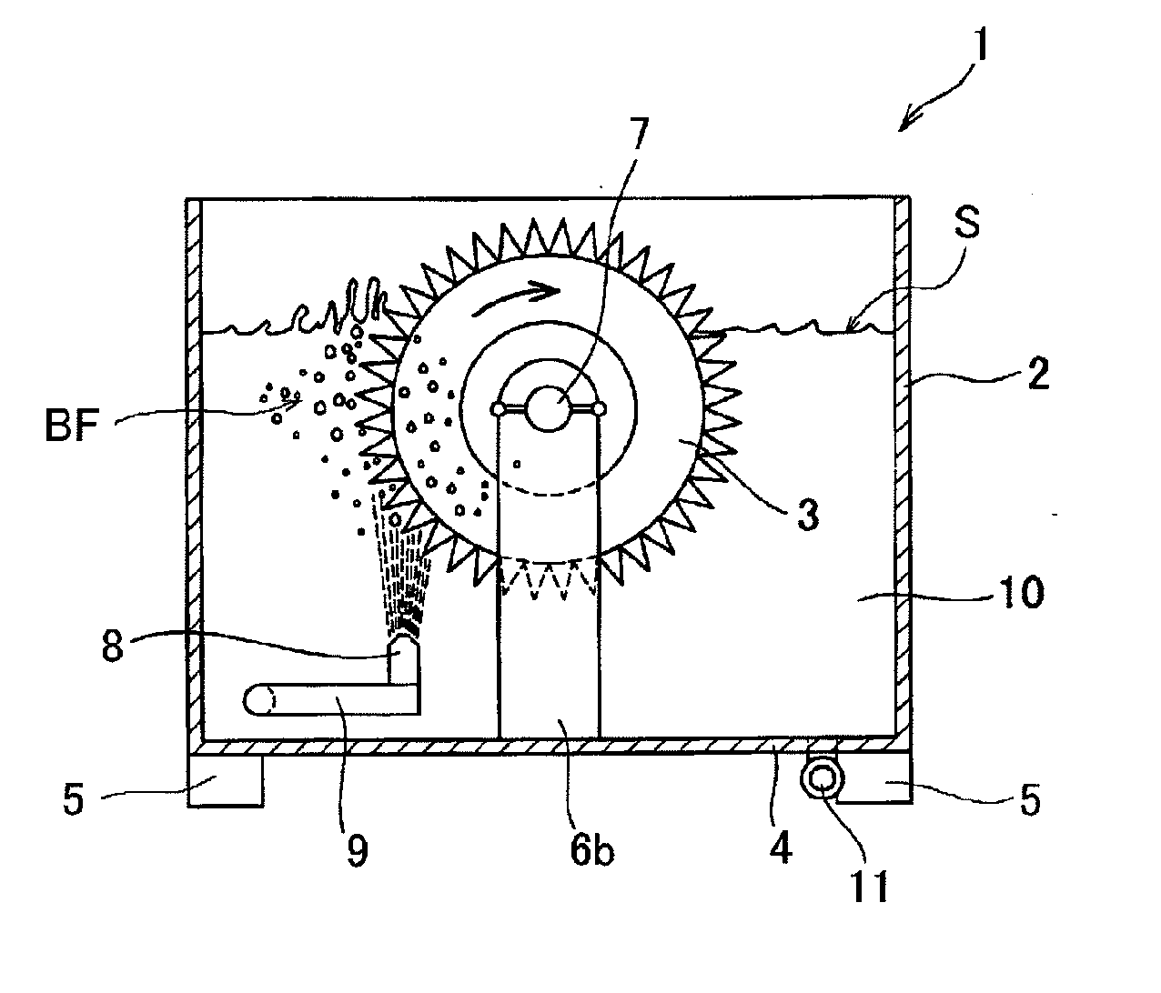
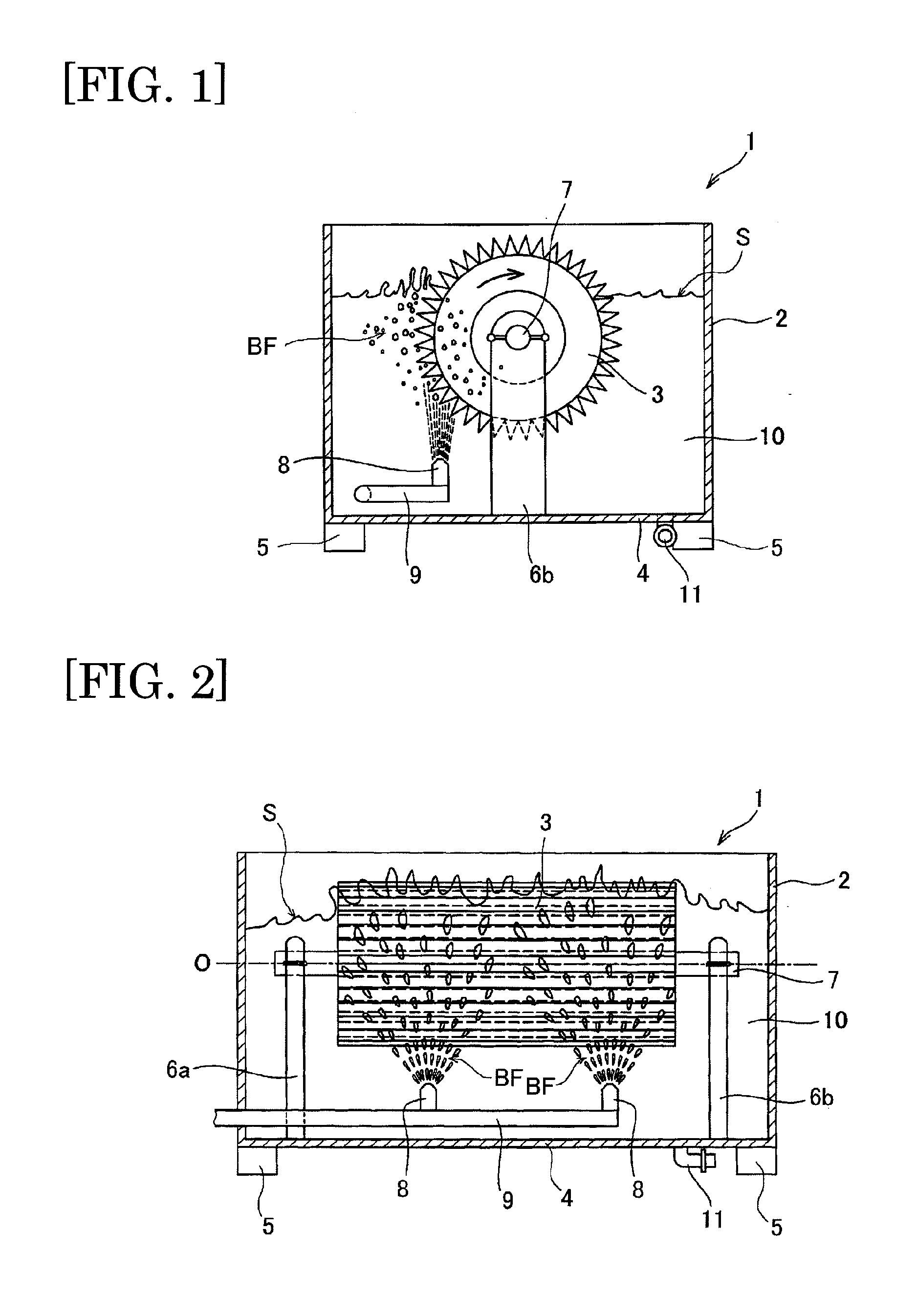
[0040]FIG. 1 is an explanatory diagram illustrating the configuration of a filter cleaning apparatus according to an embodiment of the present invention, and a cross-sectional view of the device as viewed in the lateral direction. FIG. 2 is a cross-sectional view of the filter cleaning apparatus of FIG. 1 as viewed in the front direction. The filter cleaning apparatus 1 of FIG. 1 is a cleaning apparatus for a cartridge filter used in a powder and granular material processing apparatus such as a fluidized bed granulation coating device and is formed separately from the powder and granular material processing apparatus. The filter cleaning apparatus 1 is a cleaning apparatus designed exclusively for the cartridge filter. After being removed from the powder and granular material processing apparatus, the cartridge filter is cleaned inside the filter cleaning apparatus 1.

[0041]As shown in FIGS. 1 and 2, the filter cleaning apparatus 1 is equipped with a processing container 2 formed in ...


PUM

PropertyMeasurementUnit
Pressureaaaaaaaaaa

Abstract

A filter cleaning apparatus 1 is a device designed exclusively for cleaning a cartridge filter used in a fluidized bed granulator. A cleaning liquid 10 is reserved in a processing container 2. In the processing container 2, a cartridge filter 3 is placed in the state of being immersed in the cleaning liquid 10. The filter 3 is so disposed as to be capable of rotating around a rotational axis line O that is substantially horizontal in the processing container 2. Air nozzles 8 are disposed below the cartridge filter 3. An uplift pressure of bubbles rising out of the liquid into the atmosphere is added to a bubble flow BF jetted from the air nozzles 8. As a result of the synergic effect of the jet pressure of the bubble flow BF and the uplift pressure, the filter 3 rotates in an efficient way, leading to an improvement in cleaning efficiency.

Description

TECHNICAL FIELD[0001]The present invention relates to a technique of cleaning a filter mounted on a powder and granular material processing apparatus and particularly to a cleaning process for a cartridge filter having a pleated structure.BACKGROUND ART[0002]In the field of medicine, cosmetics and food; various products are made through such processes as granulating, coating, mixing and drying of a finely divided substance like powder or powder and granular material. For such processes, a powder and granular material processing apparatus is used such as a fluidized bed granulation coating apparatus that performs a process of granulating by using a gas flow to fluidize a finely divided substance and other processes. In such a powder and granular material processing apparatus, a gas is supplied to fluidize powder and granular material; a filter is provided to separate powder and granular material from the exhaust thereof. The filter filtered out the powder and granular material that i...

Claims


Application Information

Patent Timeline
IPC IPC(8): B08B3/00
CPCB01D41/04B08B3/102B08B3/10B08B3/04
Inventor ISOBE, SHIGEMIMORIMOTO, YASUAKIHIRAI, YURIKO
Owner FREUNT IND
Why Eureka
Try Eureka