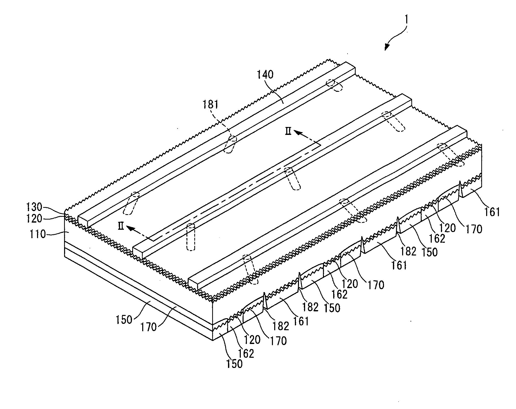
Solar cell

a solar cell and cell technology, applied in the field of solar cells, can solve the problems of low efficiency of solar cells and decrease the area on which light is incident on the substrate, and achieve the effect of reducing the angle of the via hole and increasing the sectional area

Active Publication Date: 2010-10-14
SHANGRAO JINKO SOLAR TECH DEV CO LTD
View PDF4 Cites 13 Cited by
  • Summary
  • Abstract
  • Description
  • Claims
  • Application Information

AI Technical Summary

Benefits of technology

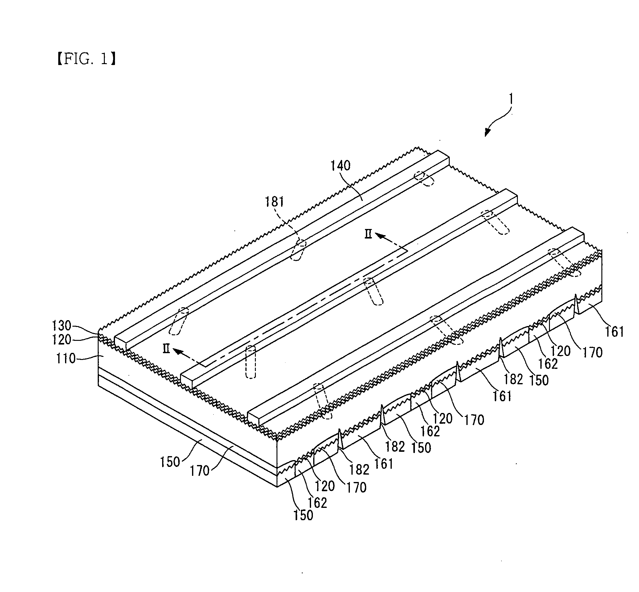
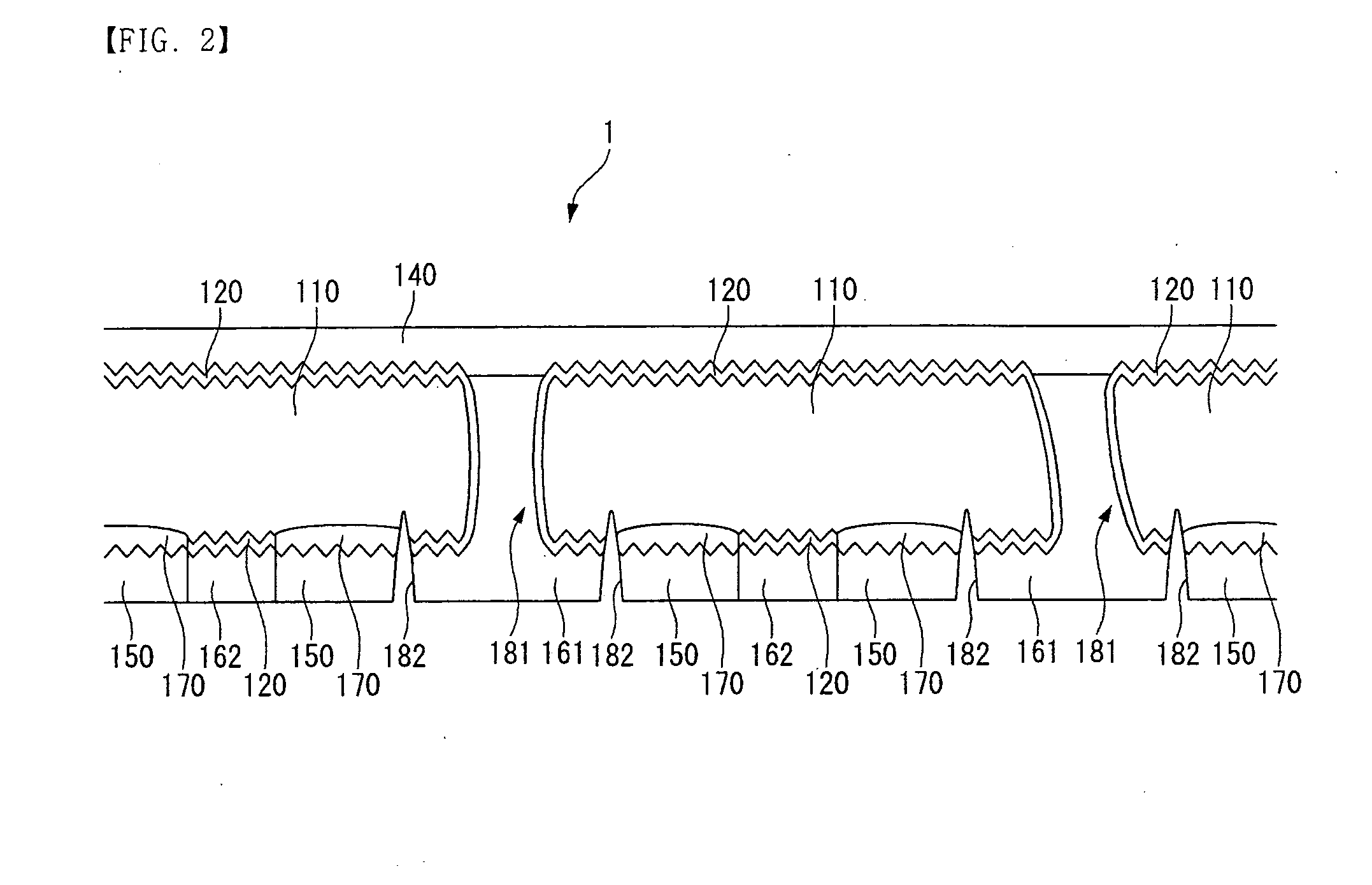
[0016]A size of the sectional area may increase as the angle of the via hole decreases.

Problems solved by technology

Accordingly, the efficiency of the solar cell is low because an area on which light is incident on the substrate is decreased by the current collectors.

Method used


Image

  • Solar cell
  • Solar cell
  • Solar cell

Examples


Embodiment Construction

[0031]Hereinafter, embodiments of the present invention will be described in detail with reference to the accompanying drawings in order for those skilled in the art to be able to implement the invention. As those skilled in the art would realize, the following embodiments may be modified in various different ways and the present invention is not limited to the embodiments. Wherever possible, the same reference numbers will be used throughout the drawings to refer to the same or like parts.

[0032]To clarify multiple layers and regions, the thickness of the layers is enlarged in the drawings. Like reference numerals designate like elements throughout the specification. When it is said that any part, such as a layer, film, region, or plate, is positioned on another part, it refers to the part being directly on the other part or above the other part with at least one intermediate part. On the other hand, if any part is said to be positioned directly on another part it refers to there be...


PUM


Abstract

A solar cell comprises a substrate configured to have a plurality of via holes and a first conductive type, an emitter layer placed in the substrate and configured to have a second conductive type opposite to the first conductive type, a plurality of first electrodes electrically coupled to the emitter layer, a plurality of current collectors electrically coupled to the first electrodes through the plurality of via holes, and a plurality of second electrodes electrically coupled to the substrate. The plurality of via holes comprises at least two via holes having different angles.

Description

[0001]Korean Patent Application No. 10-2009-0042220 filed in the Korean Intellectual Property Office on May 14, 2009, the entire contents of which are incorporated herein by reference.BACKGROUND OF THE INVENTION[0002]1. Field of the Invention[0003]The present invention relates to a solar cell.[0004]2. Discussion of the Related Art[0005]In recent years, with the expected exhaustion of the existing energy resources such as petroleum or coal, there is a growing interest in alternate energy sources which will substitute for existing energy resources. From among them, a solar cell is configured to generate electrical energy from solar energy, and it has been in the spotlight because solar energy can be easily obtained and has no problems with environmental pollution.[0006]A typical solar cell includes a substrate and an emitter layer made of semiconductors having different conductive types such as a p type or an n type, and electrodes coupled to the substrate and the emitter layer. Here,...

Claims


Application Information

Patent Timeline
Patent Type & Authority Applications(United States)
IPC IPC(8): H01L31/0236H01L31/18
CPCH01L31/02168Y02E10/547H01L31/068H01L31/02245Y02E10/546H01L31/04H01L31/18H01L31/1804H01L31/182
Inventor JANG, DAEHEEKO, JIHOONKANG, JUWANKIM, JONGHWAN
Owner SHANGRAO JINKO SOLAR TECH DEV CO LTD
Why Eureka
Try Eureka