
Arrangement of multiple pumps for delivery of process materials

a technology of process materials and arrangement of pumps, which is applied in the direction of positive displacement liquid engines, water supply installations, instruments, etc., can solve the problems of high cost of parallel arrangement of equally sized pumps, high cost of large pumps, and inability to meet the needs of process materials, etc., to achieve elimination or reduction of system disturbances, cost reduction

Inactive Publication Date: 2010-10-14
MEGA FLUID SYST
View PDF10 Cites 14 Cited by
  • Summary
  • Abstract
  • Description
  • Claims
  • Application Information

AI Technical Summary

Benefits of technology

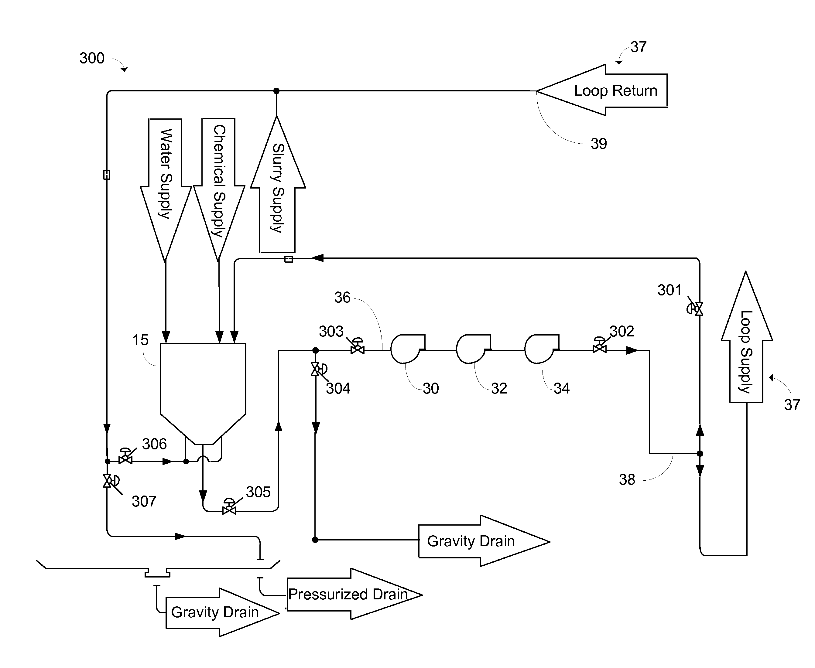
[0008]Embodiments of the present invention provide for solving the aforementioned problems by arranging multiple pumps in series rather than in parallel. One preferred embodiment includes three relatively smaller pumps arranged in series that operate simultaneously rather than individually as in the prior art. A first advantage of some embodiments of the present invention of the series arrangement over a parallel arrangement is a reduction in cost. Another advantage of some embodiments of the present invention is the elimination of a “dead leg,” or diverted supply line not in continuous use, since pumps configured in series lie along a single supply line. A further advantage of some embodiments of the present invention is the elimination or reduction of system disturbances, or perturbation, in the event of a pump failure.

Problems solved by technology

If the pump fails to provide sufficient volume or pressure, for example when the pump malfunctions, the delivery of the process materials may be interrupted or otherwise significantly compromised.
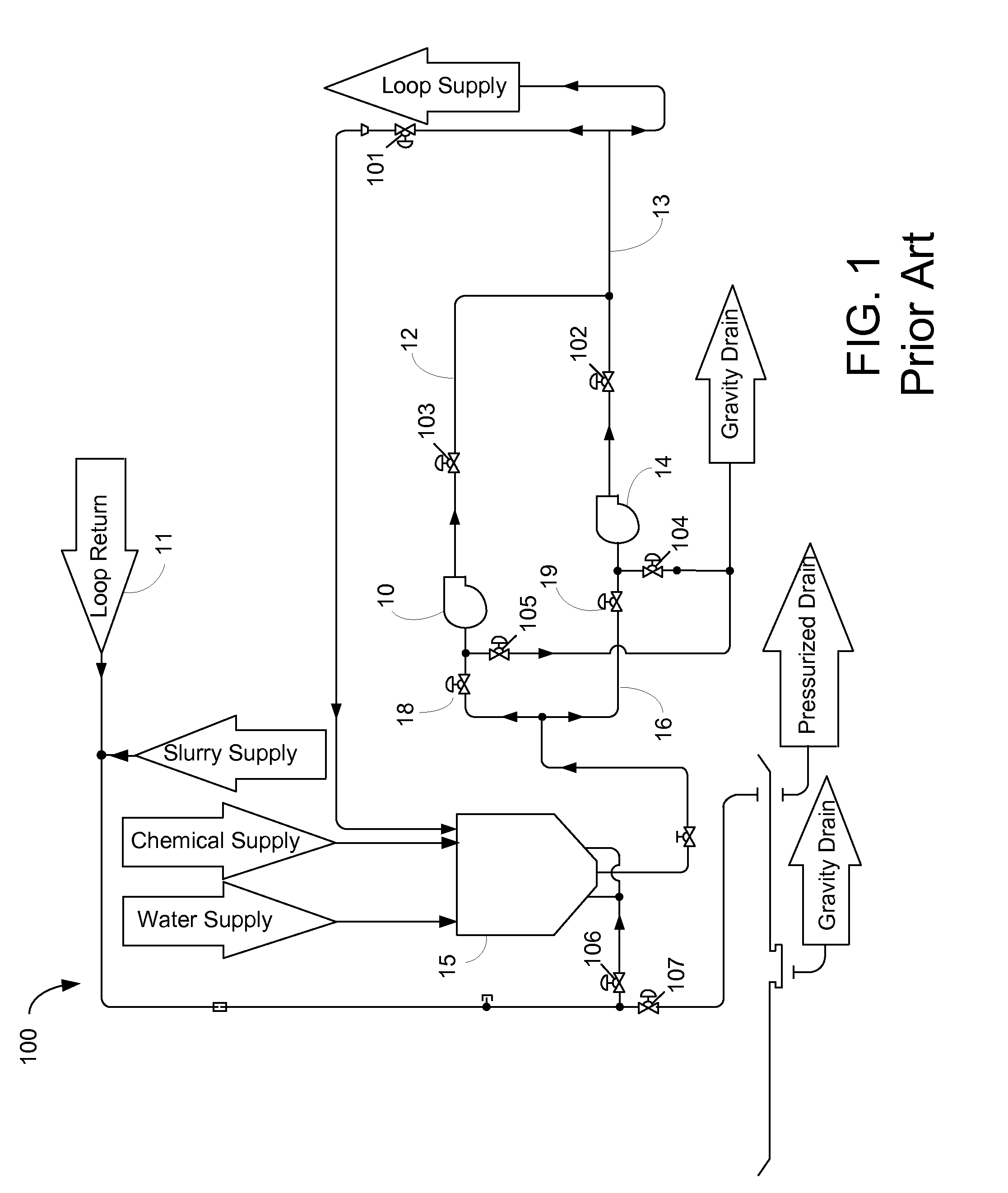
Although the redundancy of a second pump in a bulk delivery system allows for continued processing in the event of a pump failure, there are significant drawbacks to a parallel pump arrangement.
First, a parallel arrangement of equally sized pumps is expensive.
Because only one pump is propelling the process materials along the supply line at any one time, that pump in use must be large enough to carry the full load required by the system, and large pumps are expensive.
Also, because the second pump must assume the full load when the first pump fails, at least two large pumps are required in this arrangement and, therefore, the cost associated with pumps doubles.
Second, the supply line not in use forms a “dead leg” which can adversely impact chemicals.
For example, slurry particles may tend to agglomerate when little or no flow is present in a supply line that is not in use, such as with the dead leg.
When flow is eventually applied through that supply line, the agglomerates will resist evenly mixing with the provided flow of process materials, and unevenly blended process materials are typically undesirable.
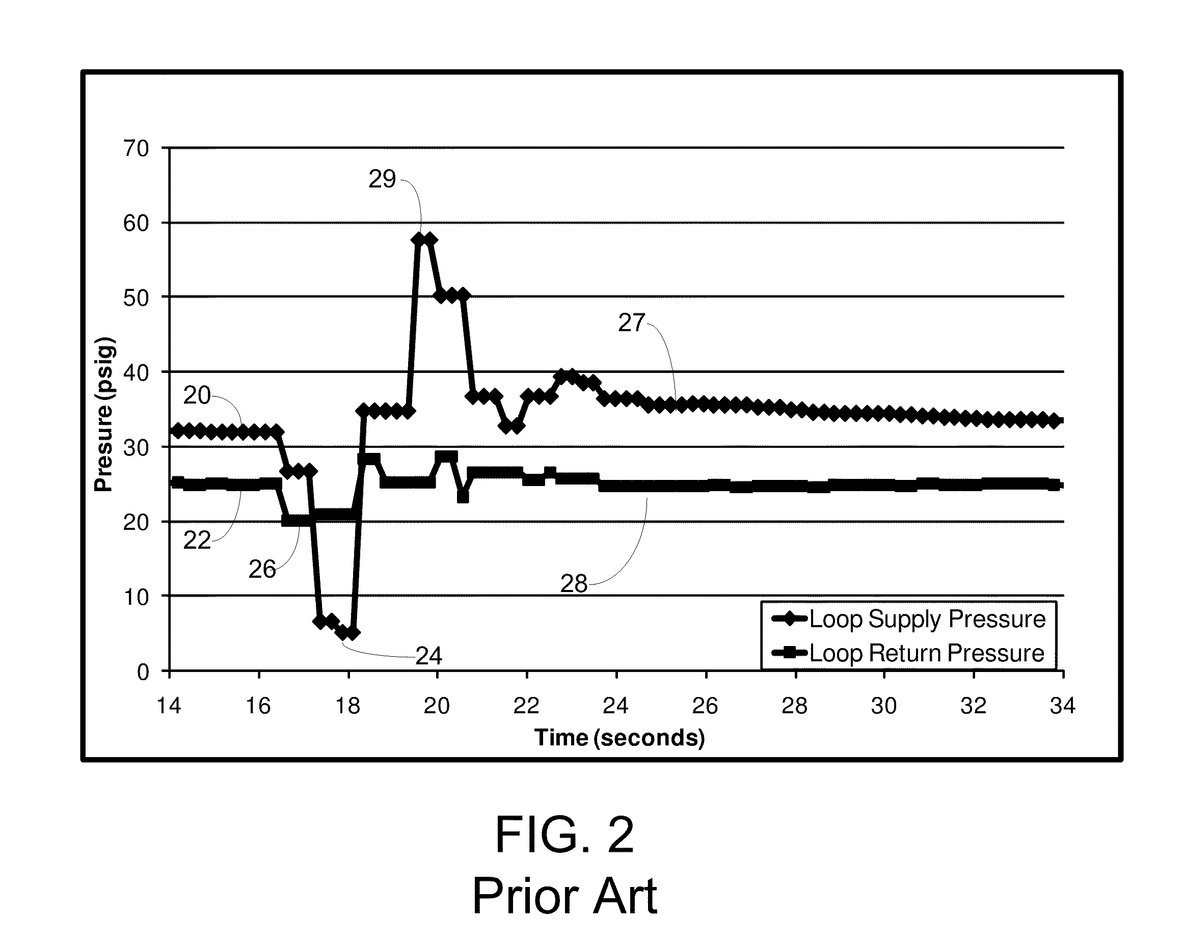
Finally, as illustrated by FIG. 2, switching service from one pump to the other introduces potentially severe pressure and flow disturbances in the system.
When a pump fails or is removed from service, the system must reroute chemicals to the second, or “redundant,” pump, and that routine invariably results in pressure and flow perturbations which may adversely affect processes at the point of use.
Because many conventional processes require precise blending of process materials, and precise delivery of those blends, even minor process variations may lead to significant differences in the batch of blended process materials, potentially rendering it useless for its intended application.
At the very least, a detected spike 29 or other perturbation in flow and pressure caused by such a switching of pumps will typically cause a system alarm to activate, possibly requiring an inconvenient and untimely manual inspection of the entire system.

Method used


Image

  • Arrangement of multiple pumps for delivery of process materials
  • Arrangement of multiple pumps for delivery of process materials
  • Arrangement of multiple pumps for delivery of process materials

Examples


Embodiment Construction

[0019]The present invention is directed to diminishing the disadvantages associated with a parallel arrangement of pumps. To this end, the present invention includes embodiments having an arrangement of multiple pumps for supplying process materials such that failure of any one of the multiple pumps is compensated for by the remaining pumps. Preferred embodiments are useful, for example, in semiconductor manufacturing, such as in a wafer fabrication system. Other uses and applications are described in U.S. Pat. No. 7,344,298 and in U.S. Pat. No. 6,923,568 to Wilmer et al. for “Method and Apparatus for Blending Process Materials” (Aug. 2, 2008), both of which are incorporated herein by reference.

[0020]FIG. 3 shows a bulk delivery system 300 with a plurality of distribution pumps arranged in series according to a preferred embodiment of the present invention. The embodiment shown in FIG. 3 uses three pumps, although as described below in some embodiments a different number of pumps co...


PUM


Abstract

A method and apparatus for delivering process materials in a bulk delivery system includes a plurality of pumps arranged in series along a material supply line, wherein the capacity of each pump is such that less than all of the pumps operating simultaneously can provide a desired level of system performance for a given application. In at least one preferred embodiment, a plurality of pumps include three pumps are arranged in series. Preferred embodiments provide several benefits over a parallel arrangement of two larger pumps including, in the case of a single pump failure, that the remaining pumps are signaled to increase speed to restore system performance to restore supply line pressure with less perturbation than that realized in a two-pump, parallel arranged system. Methods are also provided herein for determining which of the three pumps is a failed pump in such a case.

Description

This application claims priority from U.S. Provisional Patent Application No. 61 / 212,650 filed on Apr. 14, 2009, which is incorporated herein by reference in its entirety.TECHNICAL FIELD OF THE INVENTION[0001]The present invention is directed to a method and apparatus for arranging multiple pumps for the delivery of process materials.BACKGROUND OF THE INVENTION[0002]Bulk delivery systems are used, for example, to supply process equipment in the pharmaceutical, cosmetic and semiconductor industries with process materials such as liquid chemicals or slurries. Typically, a single distribution pump is used to supply the process materials. If the pump fails to provide sufficient volume or pressure, for example when the pump malfunctions, the delivery of the process materials may be interrupted or otherwise significantly compromised. To ensure the recovery from such an occurrence, bulk delivery systems typically include an extra pump (i.e., a second or redundant pump of equal capacity to ...

Claims


Application Information

Patent Timeline
IPC IPC(8): F17D1/00F04B25/00G01M19/00G01M99/00
CPCF17D1/14F04B23/04Y10T137/0324
Inventor MELCER, CHRISGRAVES, JAMIE A.FLETCHER, BRYANMURAI, KOH I.KANDIYELI, DAVID D.
Owner MEGA FLUID SYST
Learn More