Flat plate type micro heat spreading device
a heat spreading device and micro-plate technology, applied in semiconductor devices, cooling/ventilation/heating modifications, basic electric elements, etc., can solve the problems of inability to efficiently spread heat, heat spreading devices have performance limits, and heat problems that may become serious, so as to prevent a backflow of vapor bubbles, reduce the probability of compression, and improve the capillary force
- Summary
- Abstract
- Description
- Claims
- Application Information
AI Technical Summary
Benefits of technology
Problems solved by technology
Method used
Image
Examples
first embodiment
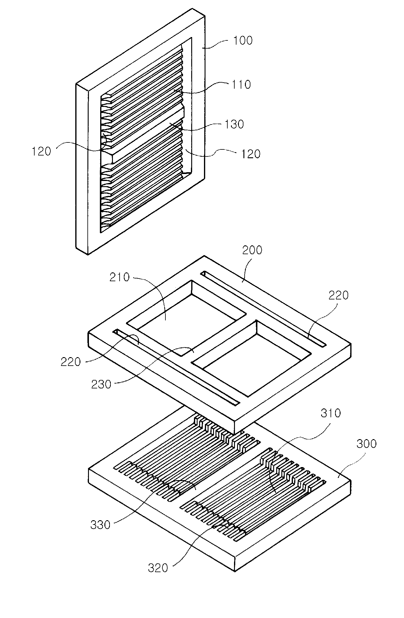
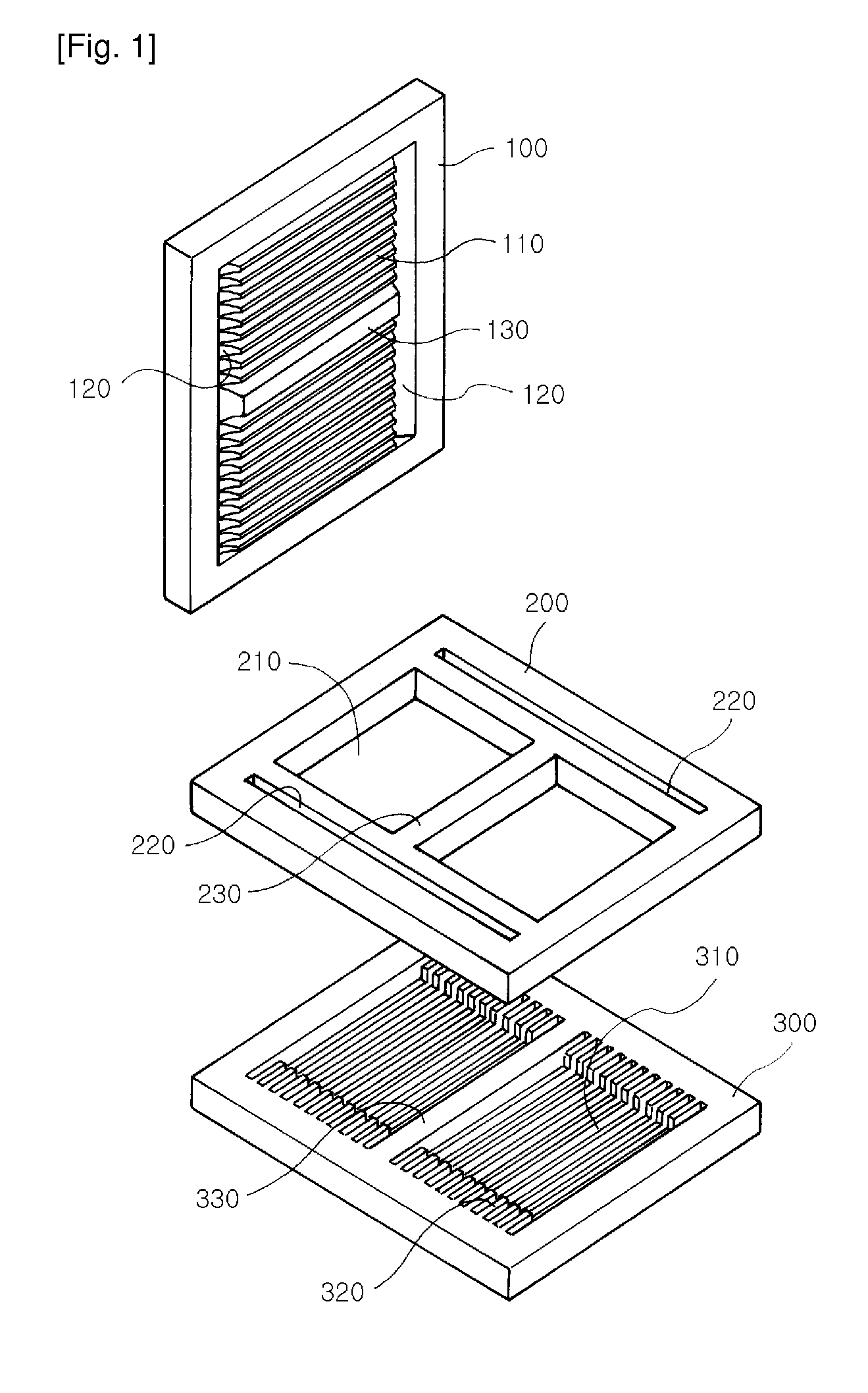
[0024]FIG. 1 is a flat plate type heat spreading device according to the present invention.
[0025]The flat plate type heat spreading device according to the embodiment is constructed by combining an upper plate 100, a middle plate 200, and a lower plate 300 with one another so as to form a closed structure. An operating fluid is injected into the closed heat spreading device. Heat is exchanged between an evaporation part of the lower plate 300 and a condensation part of the upper plate 100 through a heat transfer method through phase transition.
[0026]Specifically, the lower plate 300 evaporates the operating fluid (hereinafter, referred to as liquid) by using heat transferred from a heat source. The evaporated vapor is transmitted to the upper plate 100 through a vapor flow path 210 formed in the middle plate 200. The evaporated vapor is condensed into liquid in the upper plate 100 and transmitted to the lower plate 300 again, so as to dissipate heat of the heat source to the outside...
second embodiment
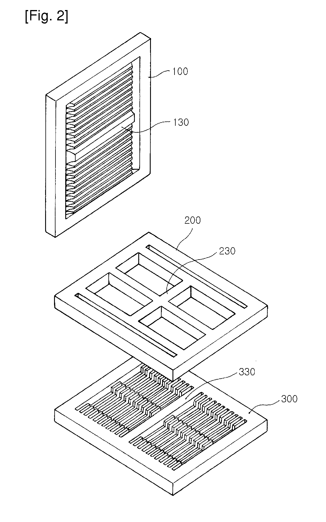
[0037]FIG. 2 is a flat plate type heat spreading device according to the present invention.
[0038]FIG. 2 illustrates a structure constructed with the upper, middle, and lower plates 100 to 300 with one another so as to form a closed structure, like the heat spreading device of FIG. 1. The operating fluid is injected into the heat spreading device with the closed structure. As described in FIG. 1, heat is exchanged between the evaporation part of the lower plate 300 and the condensation part of the upper plate 100 through a heat transfer process based on phase transition.
[0039]However, in FIG. 2, two orthogonal bridges for preventing compression in a vacuum state are formed instead of a single bridge. That is, two orthogonal bridges are formed in the evaporation space of the lower plate 300. In the upper and middle plates 100 and 200, two orthogonal bridges are also formed at a position corresponding to the two orthogonal bridges of the lower plate 300.
third embodiment
[0040]FIG. 3 is a flat plate type heat spreading device according to the present invention.
[0041]In FIG. 3, heat of the heat source is dissipated to the outside of the upper plate through the same procedure as the procedure of FIG. 1. However, the capillary structures of the upper and lower plate 100 and 200 are constructed with unidirectional grooves and new grooves perpendicular to the unidirectional grooves instead of unidirectional grooves.
[0042]Accordingly, in the upper plate 100, two liquid collection grooves 120 for collecting the condensed liquid are further formed in a direction perpendicular to the new grooves. Accordingly, in FIG. 2, the condensed liquid is collected into the liquid collection grooves formed on both sides of the upper plate.
[0043]In addition, in the middle plate 200, the liquid flow paths 220 are additionally formed at positions corresponding to the liquid collection grooves. In the lower plate 320, upper end parts with a two-step structure are further fo...
PUM
 Abstract
Description
Claims
Application Information
 - R&D
- Intellectual Property
- Life Sciences
- Materials
- Tech Scout
- Unparalleled Data Quality
- Higher Quality Content
- 60% Fewer Hallucinations
Browse by: Latest US Patents, China's latest patents, Technical Efficacy Thesaurus, Application Domain, Technology Topic, Popular Technical Reports.
© 2025 PatSnap. All rights reserved.Legal|Privacy policy|Modern Slavery Act Transparency Statement|Sitemap|About US| Contact US: help@patsnap.com


