
Dry bonding system and wearable device for skin bonding including the same

a skin bonding and wearable technology, applied in the field of skin bonding wearable devices and wearable devices, can solve the problems of insufficient adhesion force, limited application of ultrasensitive sensors, and constraints of wet bonding methods, and achieves superiority in repeated attachment and detachment, easy manufacturing, and sufficient adhesion force

Active Publication Date: 2016-07-21
RES & BUSINESS FOUND SUNGKYUNKWAN UNIV
View PDF6 Cites 14 Cited by
  • Summary
  • Abstract
  • Description
  • Claims
  • Application Information

AI Technical Summary

Benefits of technology

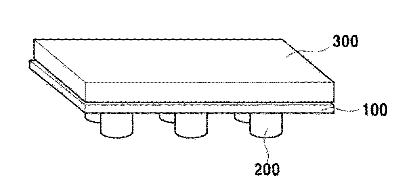
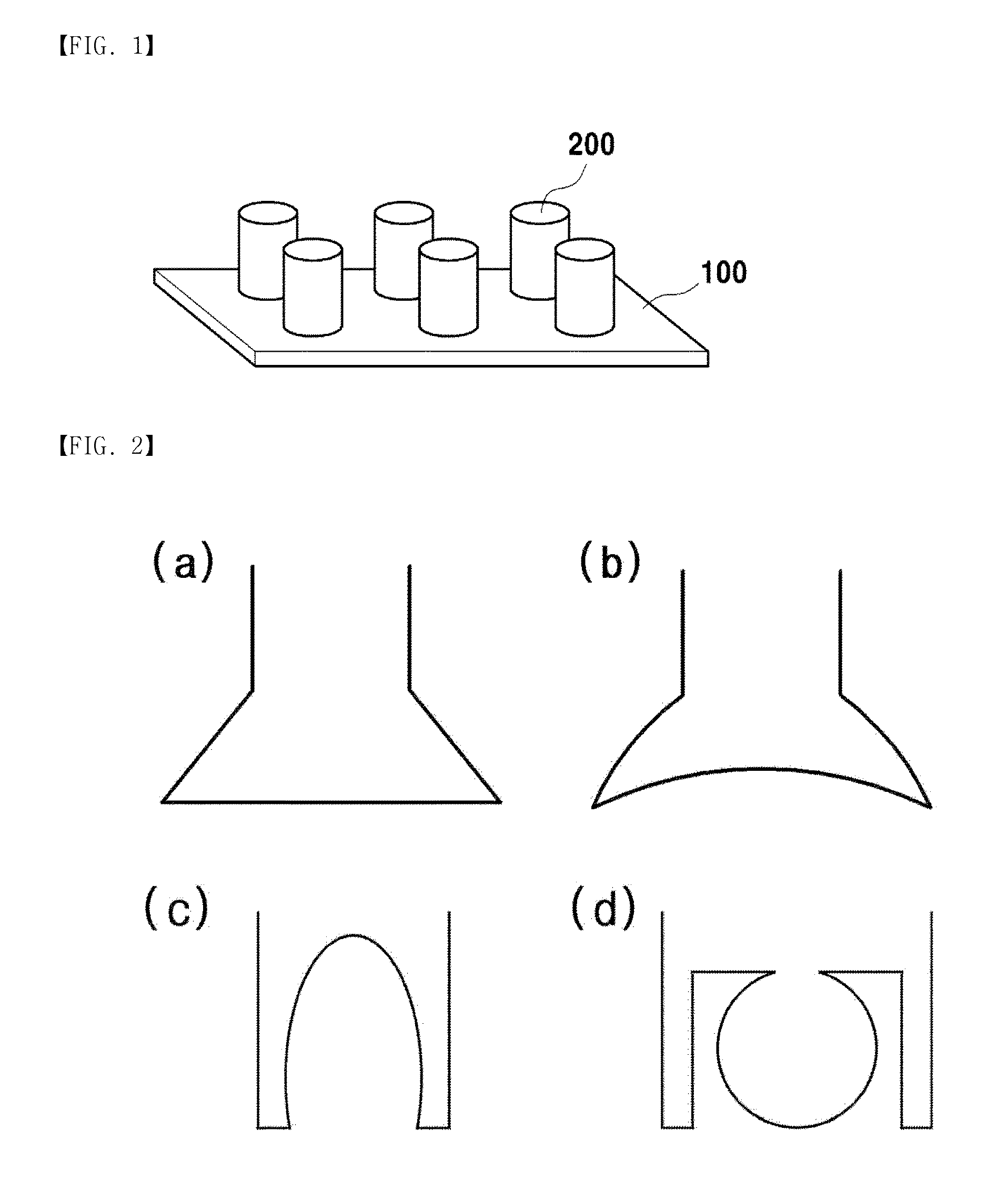
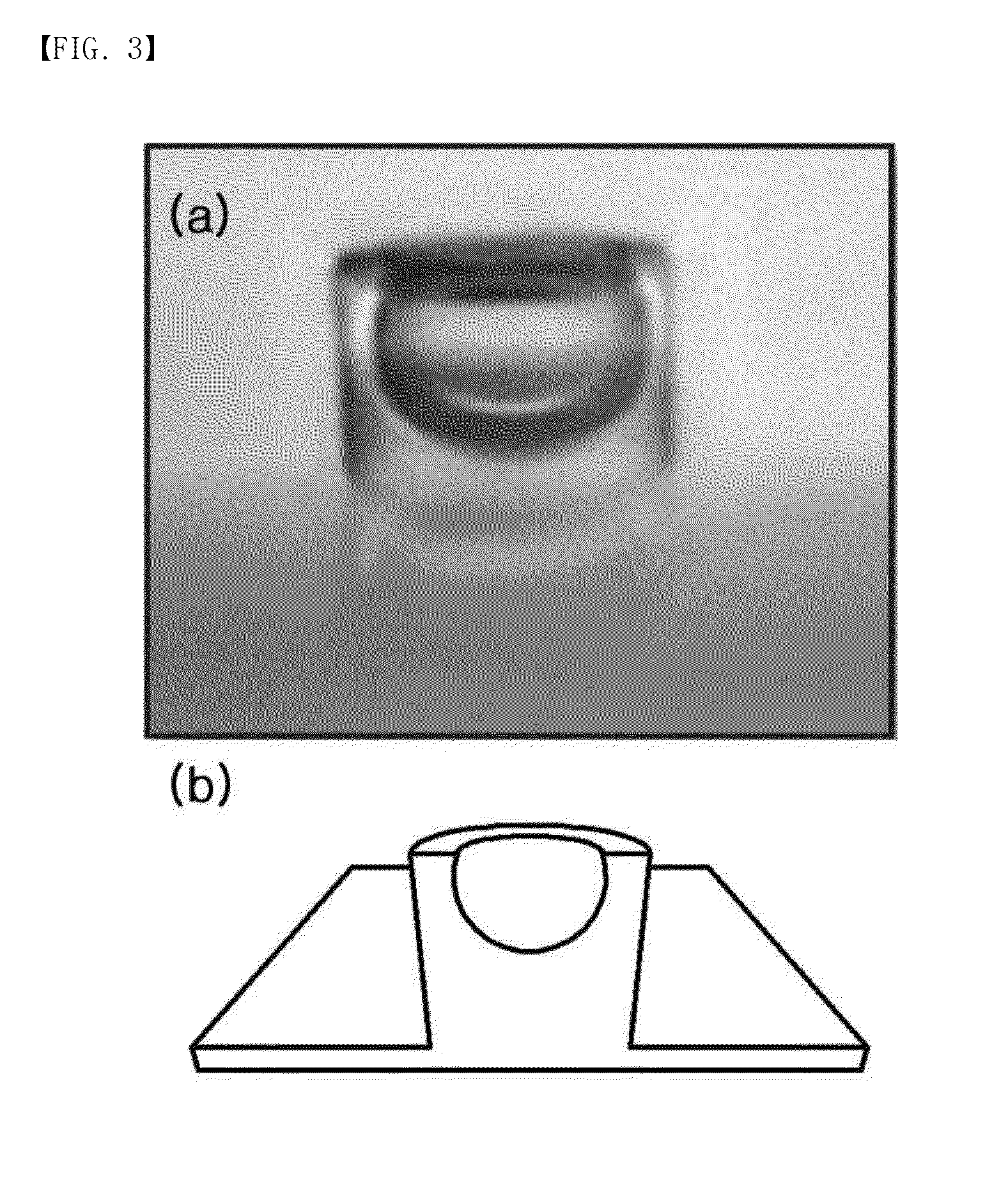
The patent describes a dry bonding system for skin bonding that uses an octopus-shaped sucker to prevent air leakage and create a pressure difference between inside and outside of the sucker. The system includes a hill-shaped embossed part that improves adhesion force and a suction force compared to a bonding system without an embossed part. The system can be combined with various sensors for wearable devices and is easy to manufacture in a large size with minimal contamination or irritation on the skin. The system also mimics the bonding system of a mollusk, allowing for adhesion force in high humidity or wet environments. The wearable device for skin bonding can improve accuracy in diagnosing physical and mental diseases by measuring biometric signals that are difficult to measure with existing sensor technology.

Problems solved by technology

Therefore, a wet bonding method has constraints in the use since detachment requires a great force or leaves some scars or skin troubles, and adhesion force is lowered in a repeated use.
However, the bio-inspired bonding system has an adhesion force which does not reach a predetermined level corresponding to the existing medical wet tape.
However, this method has insufficient adhesion force and limitation in application of an ultrasensitive sensor.
However, this method shows a lower adhesion force compared to the existing adhesive, and related researches are only focused on the separation of a patch.
However, when two nanostructure surfaces are bonded to implement nanoscale interlocking, the bonding lacks an adhesive function that is required for application of a diagnosis wearable device.
However, this technology is complicated in the manufacturing and the structure so that practical use is limited.
In addition, the use of the tattoo bonding system may cause reluctance to skin bonding and weakness in the permeability and stability.
However, this method shows a weak bonding structure against a shear stress, and thus not sufficient for being applied to a skin patch.
To summarize, various researches and developments are present about the ultrasensitive sensor technology and the dry bonding system, but still have limitation on the technical performance, and leaves much to be done in merging the ultrasensitive sensor technology and the dry bonding system to manufacture a diagnosis wearable device.

Method used


Image

  • Dry bonding system and wearable device for skin bonding including the same
  • Dry bonding system and wearable device for skin bonding including the same
  • Dry bonding system and wearable device for skin bonding including the same

Examples


examples

[0087]1. Manufacturing of a Bonding System having an Embossed Sucker Structure

[0088]Referring to FIG. 6, a bonding system having an embossed sucker structure according to Example 1 of the present disclosure is manufactured by coating a silicone master mold having a hollow cylindrical engraved structure with a UV curable polymer material, for example, liquid PUA (or PDMS that is a UV curable polymer material), pressing a PET film against the coated polymer material by using a roller such that the polymer material permeates the entire area of the master mold, and then exposing the master mold to UV rays (or heat). Then, the cured polymer material is separated from the master molder. The polymer material is cured by UV rays (or heat) to form an inverse shape of the master mold (as shown in (d) of FIG. 6). The liquid polymer material, in the process of being coated on the master mold, is coated primarily on a surface of the master mold due to a difference in surface energy. In this case...


PUM


Abstract

Disclosed are a dry bonding system and a wearable device for skin bonding including the dry bonding system.

Description

BACKGROUND[0001]1. Field of the Invention[0002]The present disclosure relates to a dry bonding system and a wearable device for skin bonding including the same.[0003]2. Discussion of Related Art[0004]Wearable devices are technology for clothing and accessories incorporating a computer and existing electronic technologies. Since the wearable device often interacts with a human body while in contact with the human body, various fields of sciences have been developed on an interface between the wearable device and the human body. According to this trend, there have been increasing demands and researches on a diagnosis wearable device that merges with a diagnosis device based on the virtue of a dry bonding technology. For example, there have been ongoing researches about application of the dry bonding technology in order to improve the stability and permeability that do not meet requirement for manufacturing a patch type sensor that measures a biometric signal, such as electrocardiogram...

Claims


Application Information

Patent Timeline
IPC IPC(8): A61B5/00A61M35/00F16B47/00A61F13/02
CPCA61B5/6834A61F13/0256F16B47/00A61F13/0253A61M35/00A61F13/025B32B3/30
Inventor PANG, CHANGHYUNPARK, YOUNG JINBAIK, SANG YUL
Owner RES & BUSINESS FOUND SUNGKYUNKWAN UNIV
Learn More