Radiation image conversion panel

a technology of radiation image and conversion panel, which is applied in the direction of conversion screen, nuclear engineering, luminescent composition, etc., can solve the problems of insufficient durability to prevent the phosphor layer, rendering the conversion panel unusable, etc., and achieves excellent durability, sufficient adhesion force, and prevent the effect of substrate corrosion

Inactive Publication Date: 2008-07-31
FUJIFILM CORP
View PDF4 Cites 5 Cited by
  • Summary
  • Abstract
  • Description
  • Claims
  • Application Information

AI Technical Summary

Benefits of technology

[0024]According to the present invention having the features described above, the radiation image conversion panel such as an imaging plate (IP) or a flat panel detector uses a polyparaxylylene layer as the separation layer for separating the phosphor layer and the substrate from each other to advantageously prevent corrosion of the substrate due to the phosphor. The radiation image conversion panel also has an oxide layer made up of a particular oxide such as silicon oxide to enable a sufficient adhesion force to be obtained between the polyparaxylylene layer and the phosphor layer while preventing its reduction, so that the radiation image conversion panel obtained will be excellent in durability and have no peeling of the phosphor layer for an extended period of time.

Problems solved by technology

Therefore, durability achieved is not sufficiently high to prevent the phosphor layer from coming off during its use, thus rendering the conversion panel unusable.

Method used


Image

  • Radiation image conversion panel
  • Radiation image conversion panel
  • Radiation image conversion panel

Examples


example 1

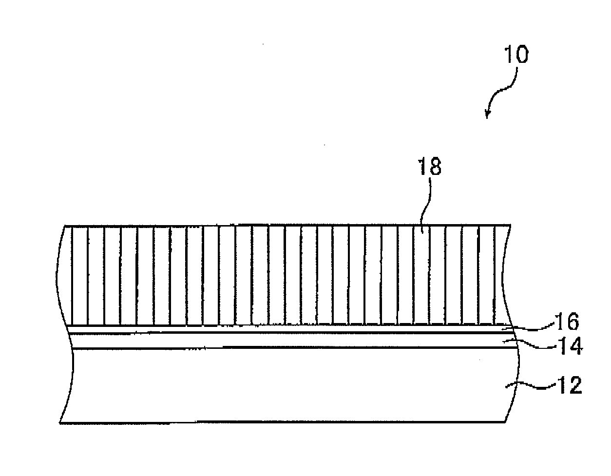
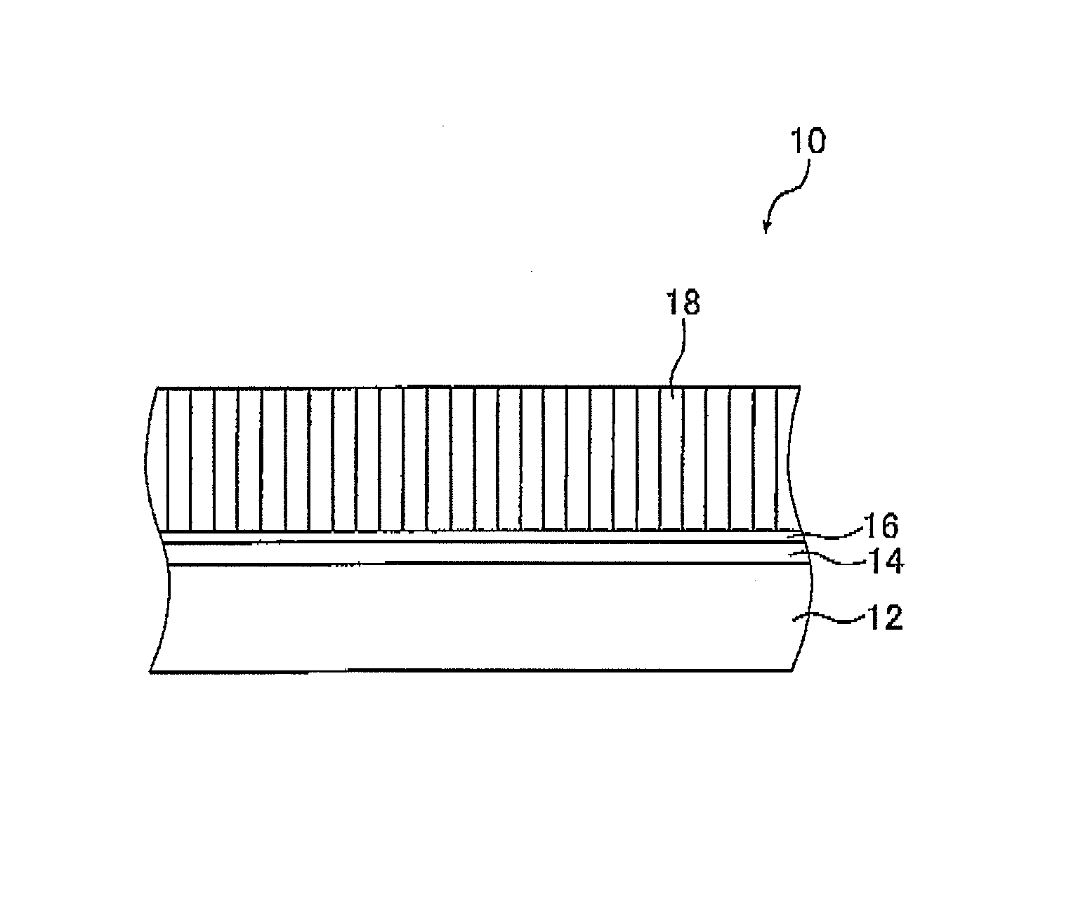
[0089]A plate made of an aluminum alloy (A5083) whose surface had been mirror-polished and which had an area of 100 mm×100 mm and a thickness of 10 mm was prepared for the substrate 12.

[0090]The surface of the substrate 12 on which the phosphor layer 18 was to be formed was cleaned with a cleaner, rinsed with water and dried. Thereafter, the substrate surface was subjected to a primer treatment using trimethoxysilylpropyl methacrylate as a primer in a vacuum device including an evaporation chamber and a substrate treatment chamber.

[0091]More specifically, the substrate 12 was loaded into the substrate treatment chamber of the vacuum device at its predetermined position and a vessel containing trimethoxysilylpropyl methacrylate was set in the evaporation chamber.

[0092]After the vacuum device was closed, the substrate treatment chamber was evacuated to a degree of vacuum of 0.4 Pa. With continued evacuation, the temperature of the evaporation chamber was increased from room temperatur...

example 2

[0106]Example 1 was repeated except that a zirconium oxide (ZrO2) film with a thickness of 0.1 μm was formed as the oxide layer 16, thereby preparing the conversion panel 10.

[0107]The oxide layer 16 was formed in the same manner as in forming the silicon oxide film in Example 1 except that zirconium oxide (ZrO2) was used as the film-forming material.

example 3

[0108]Example 1 was repeated except that a titanium oxide (TiO2) film with a thickness of 0.1 μm was formed as the oxide layer 16, thereby preparing the conversion panel 10.

[0109]The oxide layer 16 was formed in the same manner as in forming the silicon oxide film in Example 1 except that titanium trioxide (Ti2O3) was used as the film-forming material and argon gas was replaced by a gas mixture of Ar and O2 (volume ratio: 1 / 1).


PUM

PropertyMeasurementUnit
thicknessaaaaaaaaaa
thicknessaaaaaaaaaa
metallicaaaaaaaaaa

Abstract

The radiation image conversion panel includes a substrate having a metallic surface, a polyparaxylylene layer formed on the metallic surface of the substrate, an oxide layer being formed on the polyparaxylylene layer and including an oxide represented by the following formula: MxOy wherein M is an element selected from the group consisting of Si, Ge, Sn, Ti, Zr and Al, when M is Si, Ge, Sn, Ti or Zr, x is 1 and y is 2, and when M is Al, x is 2 and y is 3, and a phosphor layer formed on the oxide layer by vapor-phase deposition.

Description

[0001]The entire contents of a document cited in this specification are incorporated herein by reference.BACKGROUND OF THE INVENTION[0002]The present invention relates to a radiation image conversion panel such as an imaging plate (IP) or a scintilator panel. More specifically, the invention relates to a radiation image conversion panel that is capable of protecting the panel substrate against corrosion and is excellent in durability.[0003]Upon exposure to a radiation (e.g. X-rays, α-rays, β-rays, γ-rays, electron beams, and ultraviolet rays), certain types of phosphors known in the art accumulate part of the energy of the applied radiation and, in response to subsequent application of exciting light such as visible light, they emit photostimulated luminescence in an amount that is associated with the accumulated energy. Called “storage phosphors” or “stimulable phosphors”, those types of phosphors find use in medical and various other fields.[0004]A known example of such use is a r...

Claims


Application Information

Patent Timeline
Patent Type & Authority Applications(United States)
IPC IPC(8): H05B33/00
CPCC09K11/7733G21K2004/12G21K2004/04G21K4/00
Inventor NAKAMURA, SHIGERUHASEGAWA, KEN
Owner FUJIFILM CORP
Why Eureka
Try Eureka