Multi-branch distribution heat pipe and manufacturing method thereof

A manufacturing method and multi-branch technology, applied in the field of electronics, can solve the problems of excessive heat dissipation space, insufficient heat dissipation capacity of heat pipes, single heat pipe structure, etc., and achieve simple manufacturing process, promote market-oriented development, and strong heat transfer capacity Effect

Active Publication Date: 2015-04-29
SOUTH CHINA UNIV OF TECH
View PDF5 Cites 14 Cited by
  • Summary
  • Abstract
  • Description
  • Claims
  • Application Information

AI Technical Summary

Problems solved by technology

[0005] The primary purpose of the present invention is to propose a multi-branch distributed heat pipe with high capillary pressure, high heat transfer performance and high heat transfer performance and its manufacturing method for the single structure and insufficient heat dissipation capacity of traditional heat pipes, so as to solve the problem of Solved the problems of insufficient heat dissipation capacity of existing heat pipes and excessive heat dissipation space

Method used


Image

  • Multi-branch distribution heat pipe and manufacturing method thereof
  • Multi-branch distribution heat pipe and manufacturing method thereof
  • Multi-branch distribution heat pipe and manufacturing method thereof

Examples


Embodiment 1

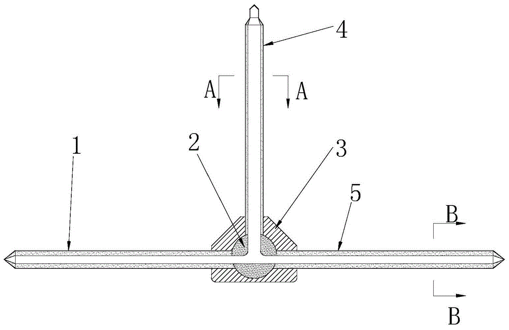
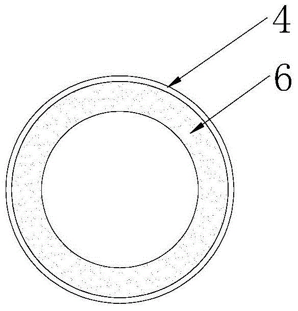
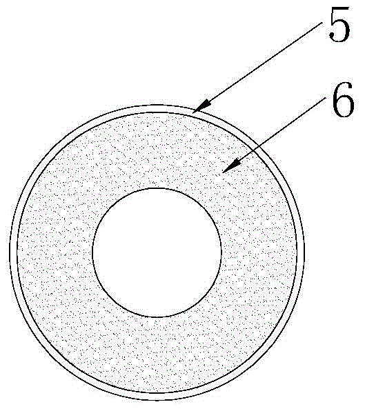
[0037] like figure 1 As shown, a multi-branch distribution heat pipe includes a multi-channel pipe joint 3, a first shell 1, a second shell 4 and a third shell 5 with one end sealed, and the multi-channel pipe joint 3 is provided with a The interface of each shell, the multi-channel pipe joint 3 is provided with a sealed cavity that communicates with each interface, and the other ends of the first shell 1, the second shell 4, and the third shell 5 are respectively plugged into the Each interface of the multi-channel pipe joint 3 forms an interconnected T-shaped structure, and the inner walls of the first shell 1, the second shell 4, and the third shell 5 are all provided with a layered porous capillary layer 6 (see figure 2 , image 3 ), the sealed inner cavity of the multi-channel pipe joint 3 is filled with a capillary connector 2 that keeps each shell connected, the first shell 1, the second shell 4, the third shell 5 The inner hole and the sealed cavity of the channel p...

Embodiment 2

[0042] A method for manufacturing a multi-branch distributed heat pipe, comprising the following steps:

[0043] (1) Use the welding process to weld and fix the first shell 1, the second shell 4 and the third shell 5 with the multi-channel shell joint 3, and then assemble and fix the sintered mandrel at one end of the third shell 5 Graphite sleeve 9 with concentric fixing effect;

[0044] (2) Prepare the first sintered mandrel 7 and the second sintered mandrel 8, the cross-sectional area of ​​the first sintered mandrel 7 is half of the cross-sectional area of ​​the second sintered mandrel 8, and the first sintered mandrel 7 and the diameter of the second sintered mandrel 8 are all smaller than the inner diameter of each shell, and one end of the second sintered mandrel 8 inserted into the second shell 4 is provided with a through hole with the same diameter as the first sintered mandrel 7, and then the Each shell and the two sintered mandrels are integrally derusted and degre...


PUM


Abstract

The invention discloses a multi-branch distribution heat pipe. The multi-branch distribution heat pipe comprises a multi-channel pipe joint, a first pipe casing, a second pipe casing and a third pipe casing, wherein one end of the first pipe casing, one end of the second pipe casing and one end of the third pipe casing are sealed; the multi-channel pipe joint is provided with connecting openings, wherein every connecting opening is used for connecting with the corresponding pipe casing; an empty sealing chamber which is communicated with the connecting openings is formed in the multi-channel pipe joint; the other end of every pipe casing is in insertion joint with the corresponding connecting opening of the multi-channel pipe joint to form a T-shaped structure, wherein the T-shaped structures are communicated with each other; the inner wall of every pipe casing is provided with a layered porous capillary layer; the inner sealing chamber of the multi-channel pipe joint is filled with capillary layer connectors which are used for maintaining the communication of the pipe casings. The invention also provides a manufacturing method of the multi-branch distribution heat pipe. According to the multi-branch distribution heat pipe and the manufacturing method thereof, the spatial hierarchical porous capillary layers and the sintering heat pipe are high in capillary force and heat transfer capability and accordingly the radial thermal resistance can be obviously improved; meanwhile the space required by heat dissipation is saved and accordingly a flexible, reliable and stable heat dissipation environment can be provided for the miniaturization development of electronic equipment; the cost is low and accordingly the multi-branch distribution heat pipe is suitable for industrialized production.

Description

technical field [0001] The invention relates to heat dissipation components in the electronic field, in particular to a multi-branch distributed heat pipe and a manufacturing method thereof. Background technique [0002] The development of modern science and technology is inseparable from the support of various types of electronic equipment. These electronic equipment have developed rapidly in the fields of aerospace, military equipment, and commercial equipment. Since the beginning of the new century, electronic equipment has gradually developed towards the direction of miniaturization, integration and high power. The more difficult it is to transfer the heat out quickly, the service life, reliability, and stability are continuously reduced, which is in strong contradiction with the direction of its development. For this reason, electronic equipment continuously puts forward stricter requirements on heat dissipation design, and requires a thermal design solution suitable f...

Claims


Application Information

Patent Timeline
Patent Type & Authority Applications(China)
IPC IPC(8): F28D15/04H05K7/20B23P15/26
Inventor 汤勇李宗涛余彬海蔡杨华袁伟陆龙生
Owner SOUTH CHINA UNIV OF TECH
Why Eureka
Try Eureka