High speed data cable with shield connection

a high-speed data and cable technology, applied in the direction of insulated conductors, power cables, cables, etc., can solve the problems of direct impact of increasing the thickness of wires on the outer diameter of cables and cable flexibility, and achieve the effect of superior properties

Active Publication Date: 2010-10-14
REDMERE TECH
View PDF8 Cites 64 Cited by
  • Summary
  • Abstract
  • Description
  • Claims
  • Application Information

AI Technical Summary

Benefits of technology

[0011]Therefore there is an object of the invention to provide an improved high speed cable

Problems solved by technology

A problem with the conventional approach of decreasing the gauge of the power and ground wires is that the resultin

Method used


Image

  • High speed data cable with shield connection
  • High speed data cable with shield connection
  • High speed data cable with shield connection

Examples


Embodiment Construction

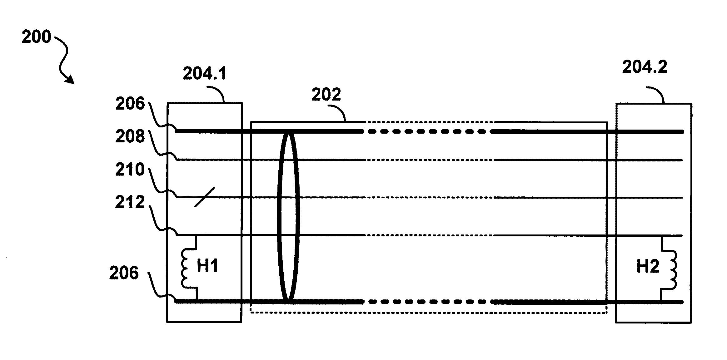
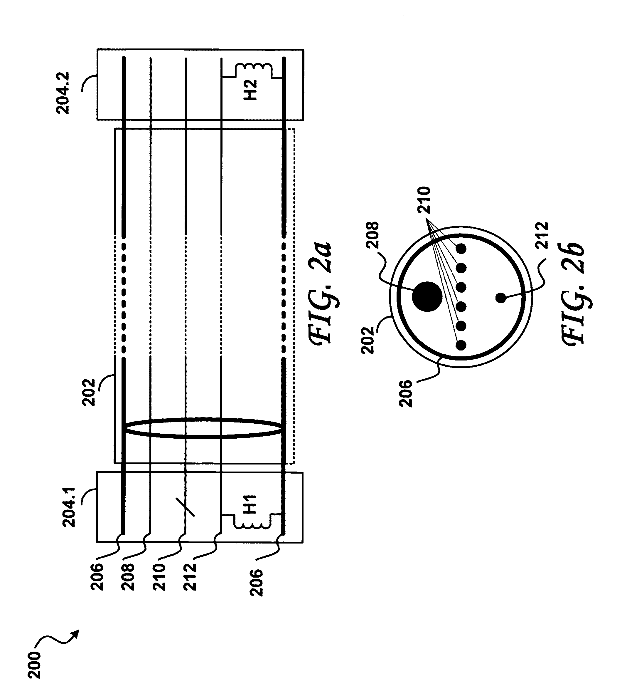
[0070]Embodiments of the present invention describe a high speed cable, in which the cable shield is used as a direct current (DC) path to reduce the combined resistance of the power and ground wires (conductors), as measured between the ends of the cable.

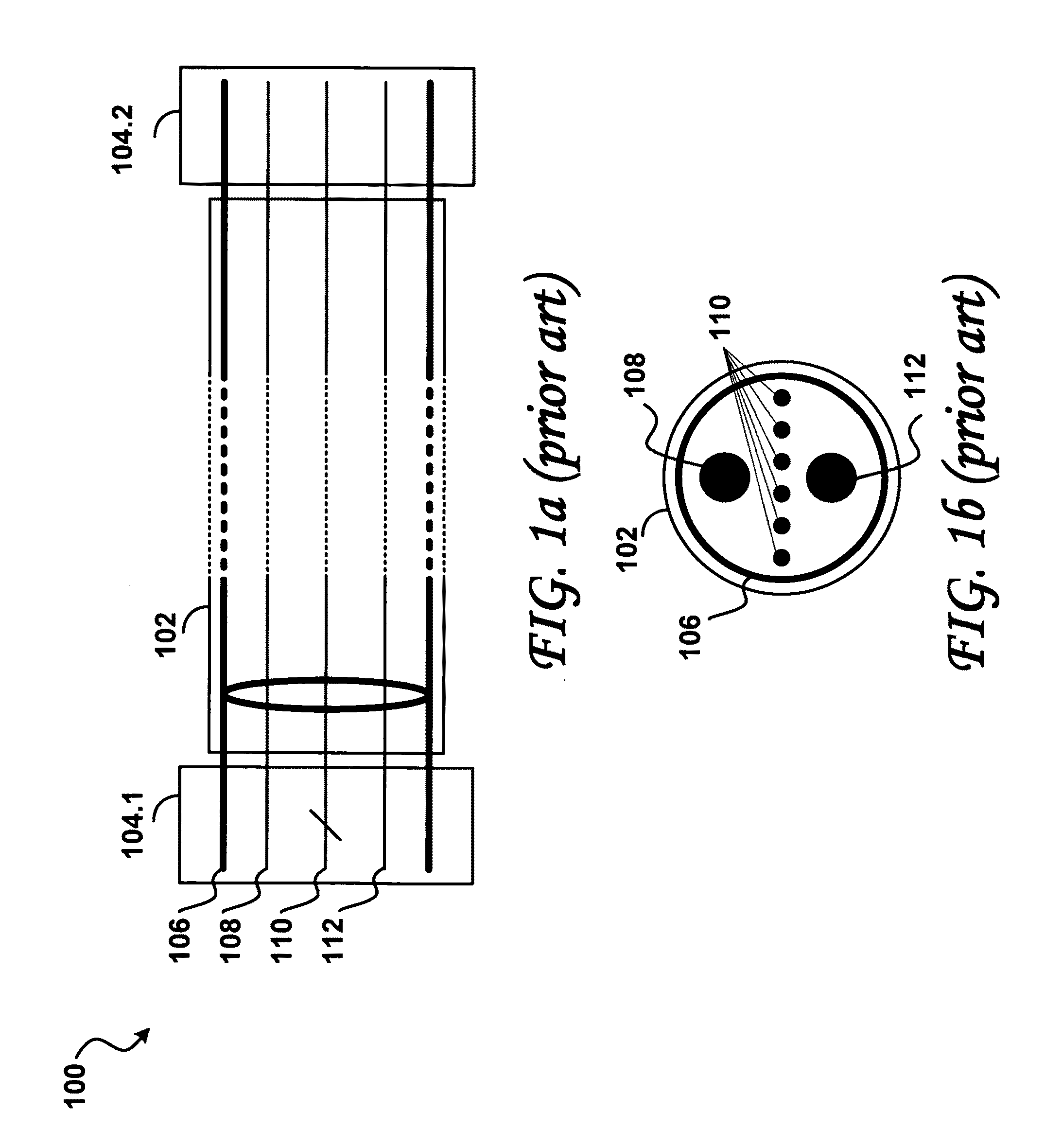
[0071]FIG. 2a shows a schematic diagram of an improved shielded high speed cable 200 according to one embodiment of the invention, including an improved raw cable 202 having improved first and second terminating ends, or terminating assemblies, 204.1 and 204.2 at respective first and second ends of the improved raw cable 202. Similar to the shielded high speed cable 100 of FIG. 1a, the improved raw cable 202 includes wires (conductors), which extend into the terminating ends 204.1 and 204.2, namely a shield (conductive layer) 206, which may be foil and / or braid, a power wire 208, a group of signal wires 210, and a thinner ground wire 212. In addition, the improved terminating ends 204.1 and 204.2 include respective first and second...


PUM

PropertyMeasurementUnit
Lengthaaaaaaaaaa
Electrical inductanceaaaaaaaaaa

Abstract

A high speed cable to carry signals according to the High-Definition Multimedia Interface and Universal Serial Bus 3.0 standards is disclosed. The cable includes a raw cable, having a conductive braid, a ground wire, signal lines; and two terminating assemblies at each end of the raw cable. The conductive braid is coupled to the ground wire in each of the terminating assemblies through a respective inductor to reduce the ground resistance of the cable, thus permitting construction of a thinner, lighter, and more flexible cable.

Description

RELATED APPLICATIONS[0001]The present application claims priority from the U.S. provisional application Ser. No. 61 / 202,869 filed on Apr. 14, 2009 for “High Speed Data Cable with Shield Connection”, the entire contents of which are incorporated herein by reference.FIELD OF THE INVENTION[0002]The present invention relates to the construction of shielded high speed data cables, which carry signal wires as well as ground and power wires.BACKGROUND OF THE INVENTION[0003]Some high speed cable standards such as the High-Definition Multimedia Interface HDMI specification (High-Definition Multimedia Interface Specification Version 1.3, published by Hitachi, Ltd., Matsushita Electric Industrial Co., Ltd., Philips Consumer Electronics, International B.V., Silicon Image, Inc., Sony Corporation, Thomson Inc., and Toshiba Corporation, Jun. 22, 2006) have specific limits on the resistance of power and ground lines in the cable. For example, in HDMI cables a limit of 1.8 ohms is specified for the ...

Claims


Application Information

Patent Timeline
IPC IPC(8): H02G15/02H01R43/00
CPCY10T29/49169H01B13/22H01B9/006Y10T29/49117H01B11/1091
Inventor HORAN, JOHN MARTINMC GOWAN, DAVID WILLIAMMC DAID, PADRAIG
Owner REDMERE TECH
Why Eureka
Try Eureka