
Removable card for a contactless communication, its utilization and the method of production.

a contactless communication and card technology, applied in loop antennas with ferromagnetic cores, waveguide devices, instruments, etc., can solve the problems of unproductive antenna area and even worsening the total transmission attributes

Active Publication Date: 2010-10-14
SMK CORP
View PDF103 Cites 76 Cited by
  • Summary
  • Abstract
  • Description
  • Claims
  • Application Information

AI Technical Summary

Benefits of technology

[0016]As for solution with one antenna it is suitable if the threads are placed spirally on the area of a quadrilateral shape. From the technological point of view the corners of such structure will be curved. One side of the quadrilateral reaches up to the marginal zone of the card's body area on the opposite side to the side of contacts, preferably up to the edge of the card. It means that the antenna's edge is placed on that edge of the card's body which is, after inserting into an appropriate slot basically outside the slot, actually as close as possible to the external edge of the slot so in fact on the edge through which the card is taken out. The opposite side of the quadrilateral does not exceed two thirds, favorably the half of the card's body area height and the lateral sides of the quadrilateral reach up to marginal zones of the card's body area, preferably up to the edge of the card. Such adjustment allows a good use of such part of the card's area which contributes to a stabile electromagnetic wave transmission. Use of deeper located part of the card to hold the antenna's area can be unproductive or even worsening the total transmission attributes.
[0020]The removable card can have the adjustment containing two antennas shaped as a spiral induction coil located opposite on the card's body area outside the zone of contacts and the coins are joined through metallic gaps in the body of the card. On the card the connection is made on the place with no obstructions by inner elements of the card with original arrangement. Both areas of the card are covered by a ferromagnetic material reaching up to the edges of the card—to the end of the areas which are opposite to the zone of contacts. Ferromagnetic foils are found at the border of the entrance gap of the slot and are not electromagnetically shaded by the metal parts of the slot case. Such adjustment creates a funnel-shaped effect of electromagnetic field flow.
[0023]To increase the functional attributes it is advantageous if the removable card is a memory card, favorably in microSD or SD or mini SD format.
[0025]Disadvantages of the present status are significantly eliminated also by a method of production of the antenna on the body of the removable card from the electrically nonconductive material according to this invention, of which the bottom line is that first a groove in the shape of a conductive path is dredged on the surface of the card's body, favorably by means of a laser beam. The thickness of the dredge cannot damage the integrity of the body of the card, usually does not exceed the depth from 0.005 mm up to 0.05 mm. Consequently, the groove is filled with a conductive material, favorable with an alloy containing gold since the contacts of the antenna are connected to a chip and on the surface or on the surface of the both areas is applied a ferromagnetic foil at least partially covering the antenna. It is suitable if the groove is filled in with a conductive material up to the height of the surrounding surface of the card.
[0026]To reach a good adhesive link of the conductive path with the body of the card and for easier groove dredging it is advantageous if the groove is dredged up to the layer of subsidized thermoplastic layer, favorably of PA6 / 6T and / or LCP and / or PBT and / or PET. It can be achieved by the choice of the basic material of the body of the card or by applying a layer of desired material on the surface of the body of the card before dredging the groove.

Problems solved by technology

Use of deeper located part of the card to hold the antenna's area can be unproductive or even worsening the total transmission attributes.

Method used


Image

  • Removable card for a contactless communication, its utilization and the method of production.
  • Removable card for a contactless communication, its utilization and the method of production.
  • Removable card for a contactless communication, its utilization and the method of production.

Examples


example 1

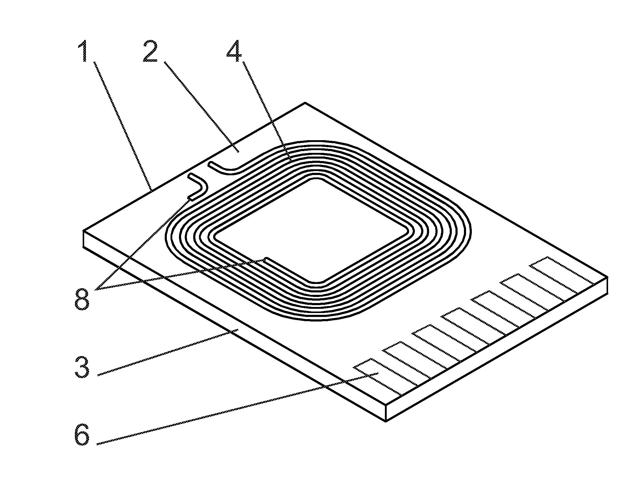
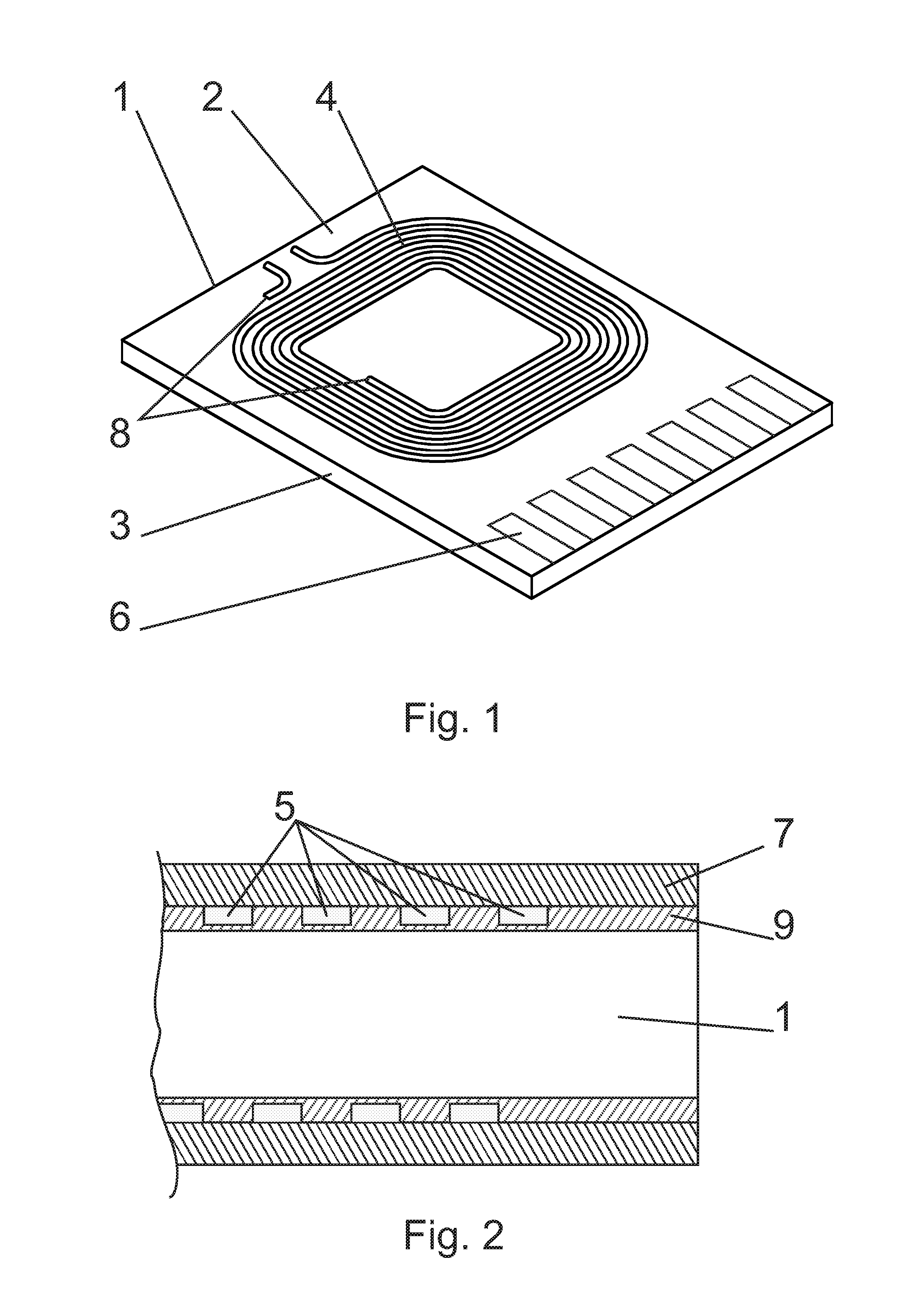
[0032]This example describes a removable card of micro SD type with the parameters 15×11×0.7 mm with two antennas 4. There are on the areas 2 of the body 1 of the card, one tuned in a frequency of 13.5 MHz, second one tuned in a frequency of 13.6 MHz. Antenna's elements are made of spiral induction coils basically placed opposite on the areas 2 of the card. Coils are joined through metallic gaps 8 in the card on the body 1 of the card where the gap 8 with the joint is not an obstruction to inner elements of the card. The overall impedance attributes of the antenna 4 are set to have resonant frequency of 13.56 MHz after inserting into a slot of the mobile phone. By creating antenna 4 the adjustable parameter is the thickness of the conductive path 5, the size of the gap between the conductive paths 5 and the number of threads 10 of the coils. The first contact of the first antenna 4 is connected to exit contacts of the chip; the second contact of the first antenna 4 is connected to g...

example 2

[0034]According to schematic, scale-less pictures 3 to 5 the antenna 4 is winded up on the body 1 of the card by across the circumference winding. The body 1 of the card contains of LCP polymer type. The conductive path 5 crosses the area 2 of the body 1 of the card, in fact vertically to the edge 3 of the card. Further it continues aslant under 45 degree angle along the edge 3 of the body 1 of the card to the opposite area 2 of the body 1 of the card from where it leads across to the other edge 3 of the body 1 of the card and so it is repeatedly winded up onto the body 1 of the card. The conductive paths are mutually parallel, in this example with the width of 0.15 mm. Between the conductive path 5 winding on the upper area 2 and continuous winding on the lower area 2 is the movement of 0.7 mm. The slope of the conductive path 5 on the edge 3 of the body 1 of the card allows the movement of the continuation of the conductive path 5 on the opposite areas 2 of the card. The gap betwe...

example 3

[0035]A removable card in this example is a memory card with a body 1 of micro SD shape with parameters of approximately 15 mm×11 mm. It contains one antenna 4 created on one area 2 of the card. The antenna 4 consists of eight threads 10 and both areas 2 of the card are covered by a ferritic foil with the thickness of 100 μm with the antenna 4 is placed under the foil. Relative permeability of the ferritic foil is from 50-150. Covered are almost all the areas 2 of the card apart from the contact 6 zone.

[0036]Threads 10 are 100 μm wide with 100 μm wide gaps between the threads 10. The threads 10 of the antenna 4 are shaped into the borders of the rectangle with parameters of 5 mm×8.5 mm and with curved corners. The antenna 4 approaches with its three sides the marginal zones of the area 2 of the body 1 of the card. One side of the rectangle outlining the external borders of the antenna 4 reaches up to the marginal zone of the card's body 1 area 2 on the side opposite to the side of c...


PUM

PropertyMeasurementUnit
Thicknessaaaaaaaaaa
Lengthaaaaaaaaaa
Lengthaaaaaaaaaa

Abstract

Removable card for a contactless communication contains an antenna (4) formed of threads (10) placed on the external surface of the body (1) of the card and covered by a layer (7) of a ferromagnetic material. In advantageous adjustment the antenna (4) contains on one area (2) of the card eight threads (10) and both areas (2) of the card are covered by a layer (7) of a ferritic foil. The antenna (4) is connected to the series with element (12) with capacity and the resistance (11) on the other side. Resonant circuit is tuned in for the final frequency from 13.0 to 15.0 MHz. The signal from the antenna (4) is read between the first and the second thread (10) from the side of the element (12) with capacity. The production method for the antenna on the body of the removable card resides in the fact that a groove of the conductive path (5) shape is dredged on the surface of the card's body (1), the groove is filled with a conductive material and a ferromagnetic material layer (7) is applied on the surface of the area (2) covering the antenna (4).

Description

FIELD OF INVENTION[0001]The present invention relates to a removable, basically a flat card, in particular a memory card adjusted to a contactless radio communication, mainly NFC communication for the need of authorized processes executed by mobile communication devices. The invention also describes the utilization of the card and the method of production by means of adapting and supplementing a common construction of a removable card, mainly a memory card to a card with desired elements.PRESENT TECHNOLOGY STATUS[0002]Various memory card formats are widely used in a broad range of technical means such as digital cameras, mobile phones, computers. An appropriate slide in connector, slot in a device corresponds to a given standardized memory card format. Due to industrial production the removable memory cards are spread widely and the communication devices, mobile phones commonly contain an appropriate slot for a memory card insertion.[0003]At the present, known are no such cards whic...

Claims


Application Information

Patent Timeline
IPC IPC(8): G06K19/067H01P11/00H01Q7/00
CPCG06K19/07732G06K19/07749G06K19/07771G06K19/07779Y10T29/49016H01Q1/2225H01Q1/2275H01Q7/06G06K19/07783H05K1/117H05K1/165H05K2201/10098H05K2201/10159G06K19/077
Inventor FLOREK, MIROSLAVMASARYK, MICHAL
Owner SMK CORP
Features
  • Generate Ideas
  • Intellectual Property
  • Life Sciences
  • Materials
  • Tech Scout
  • Unparalleled Data Quality
  • Higher Quality Content
  • 60% Fewer Hallucinations
Learn More