Hydrodynamic seal with improved exclusion and lubrication

a technology of lubrication and sealing, applied in the direction of engine seals, mechanical devices, engine components, etc., can solve the problems of reducing the viscosity of lubricant films, and encouraging abrasive invasion of dynamic sealing interfaces, etc., to achieve the effect of reducing torque, improving environmental exclusion, and reducing wear and heat generation

Inactive Publication Date: 2010-10-14
KALSI ENG
View PDF65 Cites 10 Cited by
  • Summary
  • Abstract
  • Description
  • Claims
  • Application Information

AI Technical Summary

Benefits of technology

[0044]One objective of the preferred embodiment of the present invention is to provide a hydrodynamic rotary seal having improved environmental exclusion. Another objective is reduced torque, for reduced wear and heat generation. Another objective is improved distribution of lubricant across the dynamic sealing interface, and correspondingly reduced seal wear, particularly in seals that are exposed to skew-resisting axial confinement and / or high differential pressure that may be acting from either side of the seal. Another objective is to enable the use of hydrodynamic inlet geometry that better accommodates high temperature operation in conditions of skew-resisting axial confinement.

Problems solved by technology

Such waviness can encourage abrasive invasion of the dynamic sealing interface.
Certain operating conditions can also result in undesirable increases in interfacial contact pressure.
When lubrication thus decreases, the seal generates undesirable heat due to increasing asperity friction, causing a loss of lubricant film viscosity and seal wear.
The friction further increases seal temperature, compounding the problem.

Method used


Image

  • Hydrodynamic seal with improved exclusion and lubrication
  • Hydrodynamic seal with improved exclusion and lubrication
  • Hydrodynamic seal with improved exclusion and lubrication

Examples


Embodiment Construction

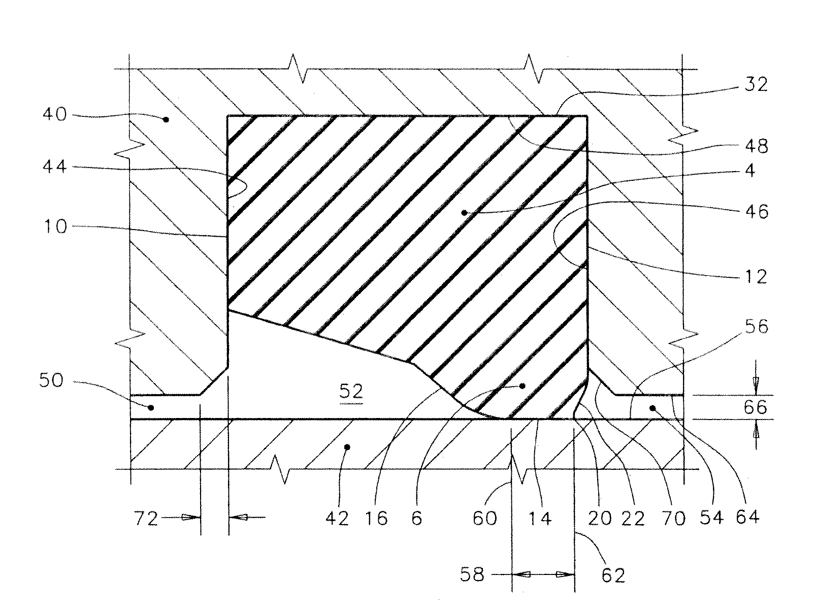
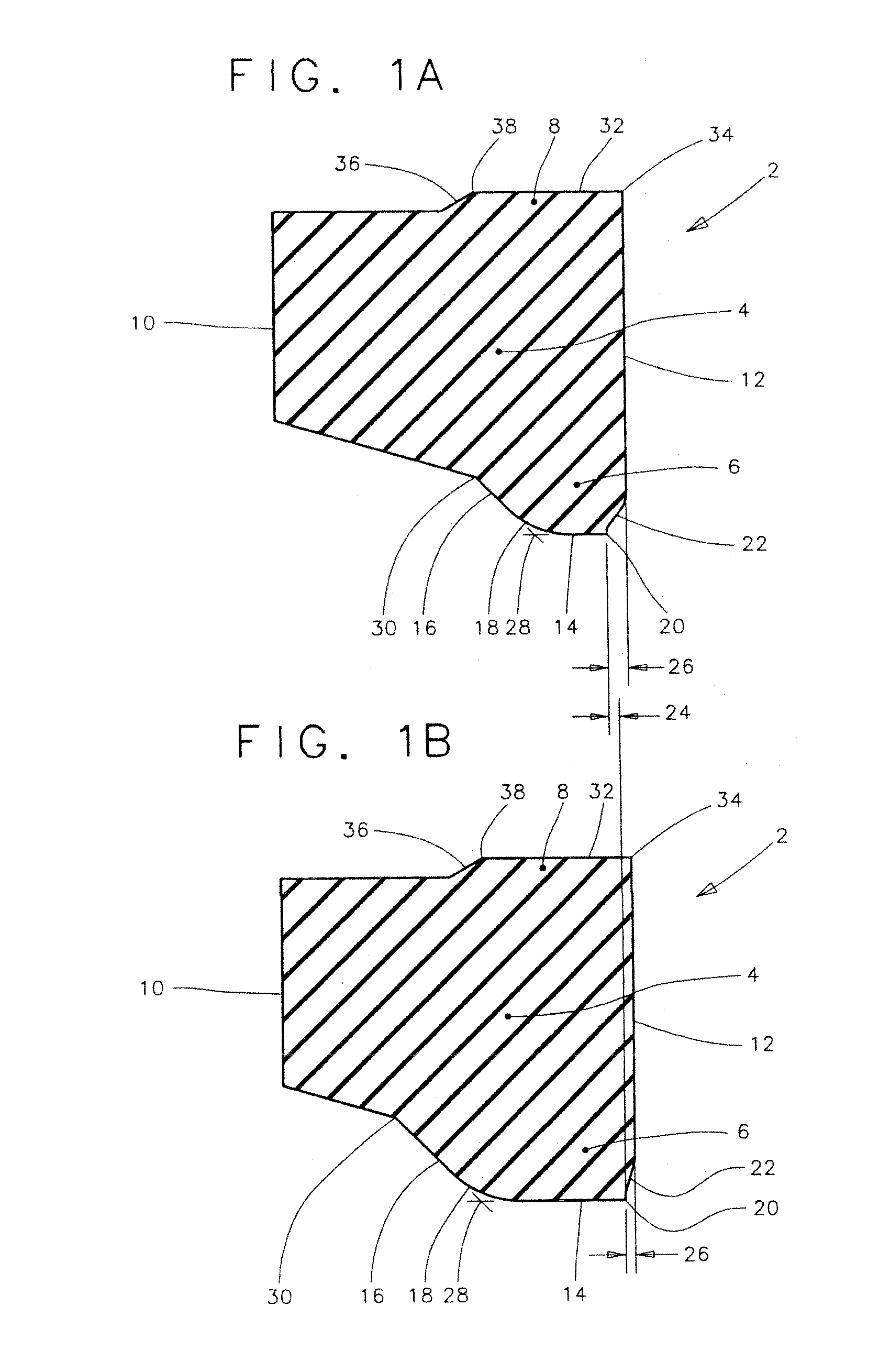
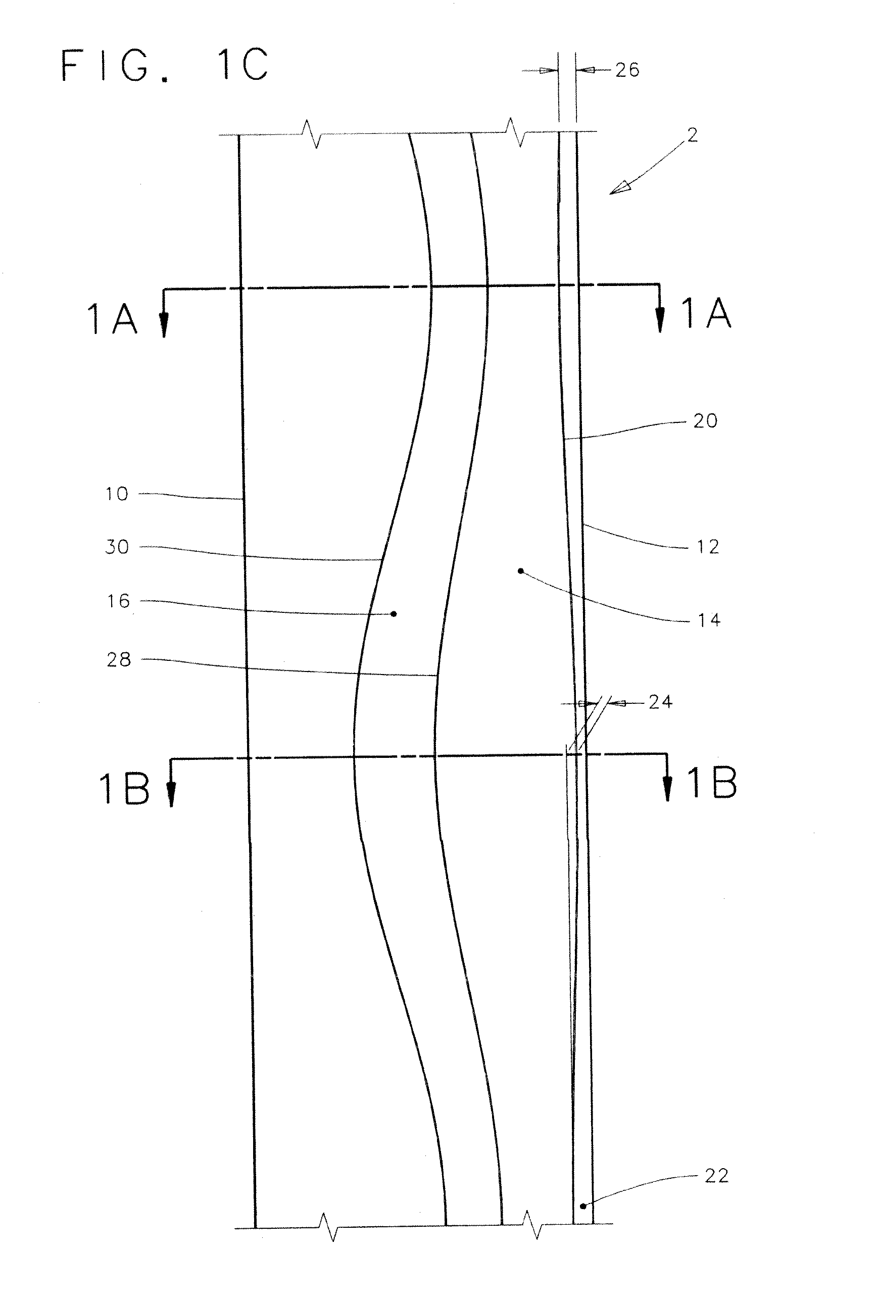
[0054]The ring-like rotary seal according to the preferred embodiments of the present invention is generally referred to as reference number 2 in the drawings. Features throughout this specification that are represented by like numbers have the same basic function.

[0055]FIGS. 1A-1F

[0056]FIGS. 1A-1F are views representing a preferred embodiment of the present invention, and should be studied together, in order to attain a more complete understanding of the invention.

[0057]FIGS. 1A & 1B

[0058]FIGS. 1A and 1B are fragmentary views that represent the cross-sectional configuration of the rotary seal 2 at respective first and second locations before installation, and FIG. 1C is a fragmentary view of the seal that identifies the cutting planes that relate to the cross-sections of FIGS. 1A and 1B. FIGS. 1D and 1E are fragmentary views that represent the cross-sectional configuration of the rotary seal 2 at the same first and second locations after installation.

[0059]Referring now to FIGS. 1A...


PUM


Abstract

A hydrodynamic sealing assembly including a first machine component defining a seal groove and a second machine component having a rotatable surface that is rotatable relative to the first machine component. A hydrodynamic seal including a seal body of generally ring-shaped configuration having a circumference and the seal body includes a sealing lip having a sealing surface contacting the relatively rotatable surface to establish a sealing interface between the sealing lip and the relatively rotatable surface. The sealing lip includes an exclusion edge of abrupt substantially circular form that is substantially aligned with a direction of relative rotation between the sealing lip and the relatively rotatable surface in a compressed, installed condition of the seal and wherein the exclusion edge is non-circular and slightly wavy in an uncompressed, uninstalled condition of the hydrodynamic seal.

Description

CROSS-REFERENCE TO RELATED APPLICATIONS[0001]This application claims the benefit of U.S. Provisional Application Ser. No. 61 / 212,179 filed Apr. 8, 2009, entitled “Rotary seal with improved environmental exclusion,” and claims the benefit of U.S. Provisional Application Ser. No. 61 / 283,277 filed Nov. 30, 2009, entitled “Seal Carrier,” and claims the benefit of U.S. Provisional Application Ser. No. 61 / 284,179 filed Dec. 14, 2009, entitled “Pressure-balanced floating seal carrier.” Provisional Application Ser. Nos. 61 / 212,179, 61 / 283,277, and 61 / 284,179 are incorporated by reference herein for all purposes.BACKGROUND OF THE INVENTION[0002]1. Field of the Invention[0003]This invention relates to hydrodynamic rotary seals that are used to retain lubricant and exclude the environment in diverse applications. More specifically, this invention relates to features that improve exclusion edge circularity and regulate contact pressure at the dynamic sealing interface for improved abrasive excl...

Claims


Application Information

Patent Timeline
Patent Type & Authority Applications(United States)
IPC IPC(8): F16J15/32
CPCF16J15/164F16J15/3244F16J15/324
Inventor DIETLE, LANNIE LAROY
Owner KALSI ENG
Why Eureka
Try Eureka