Power control circuit and method

Active Publication Date: 2010-10-14
GE LIGHTING SOLUTIONS LLC
View PDF9 Cites 29 Cited by
  • Summary
  • Abstract
  • Description
  • Claims
  • Application Information

AI Technical Summary

Benefits of technology

[0013]In accordance with an aspect of the present invention a light source is provided. The light source includes a controllable power source for supplying power to a non-linear light-emitting load; a current sensing circuit connected to the non-linear light-emitting load that generates a current signal representing the current flowing through the non-linear light-emitting load; a voltage sensing circuit connected to the non-linear light-emitting load that generates a voltage signal representing the voltage across the non-linear light-emitting load; a power sensing circuit connected to the current and voltage sensing circuits that receives the current and voltage signals and measures the power consumption of the light-emitting load and generates a variable power-representative signal; and a power feedback control circuit connected between the power sensing circuit and the controllable power source through which the power source is controlled in relation to the variable power-representative signal to maintain the power consumption of the light source substantially constant.
[0014]In accordance with another aspect of the present invention a method of maintaining the intensity and power consumption of a light source substantially constant is provided. The method includes supplying a controllable dc voltage and current to a non-linear light-emitting load; multiplying an output forward voltage and

Problems solved by technology

Therefore, voltage feedback control may be detrimental to the service life of such an LED.
Also, a fixed LED output current presents the following drawbacks: at higher temperature the LED forward voltage decreas

Method used


Image

  • Power control circuit and method
  • Power control circuit and method
  • Power control circuit and method

Examples


Embodiment Construction

[0025]Although the exemplary embodiments of the present invention will be described hereinafter with reference to a light source such as a light-emitting diode (LED) traffic signal lamp, it may be used in other LED lighting applications such as rail signals, signage, commercial refrigeration, general Illumination, vehicle lighting, variable message and many other applications, and it should be understood that this example is not intended to limit the range of applications of the present invention.

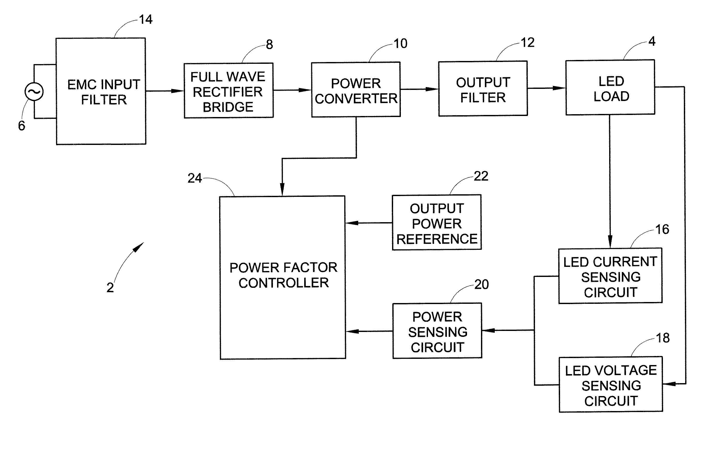
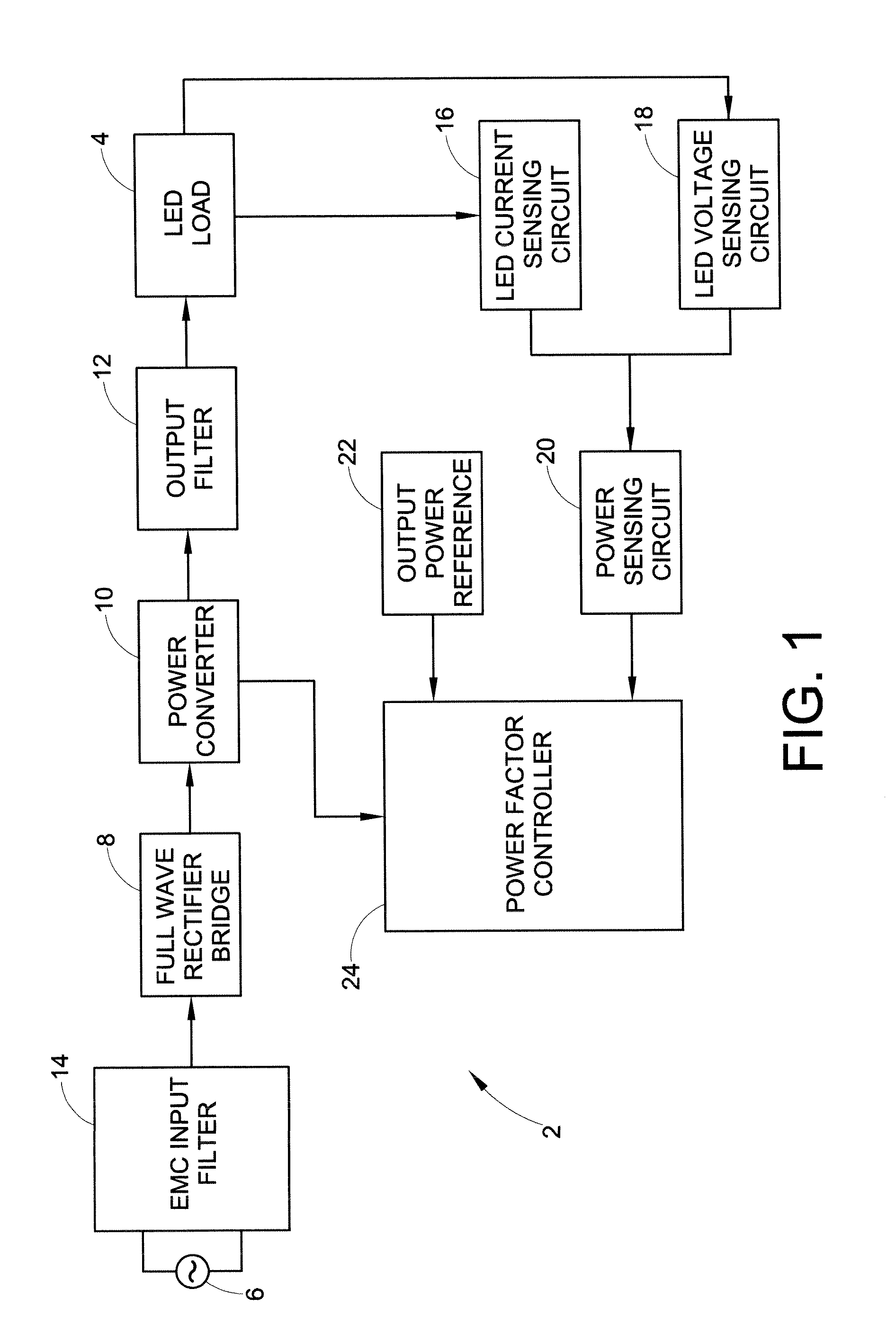
[0026]Referring now to the drawings wherein the showings are for purposes of illustrating the exemplary embodiments only and not for purposes of limiting the claimed subject matter, FIG. 1 shows a block diagram of a light source 2, such as an LED traffic signal lamp. The light source 2 includes a non-linear load 4 comprising at least one set of LEDs. The set is typically formed of a plurality of subsets of LEDs, wherein the LEDs within each subset are serially interconnected. The subsets of...


PUM


Abstract

A light source with substantially constant intensity and power consumption is provided. The light source includes a controllable dc voltage and current source; a non-linear light-emitting load supplied with dc voltage and current from the controllable dc voltage and current source; a current sense circuit connected in series with the non-linear light-emitting load; a variable LED forward voltage (varying with temperature, binning batch, aging) sensor circuit; a multiplier operative to measure a power-representative signal; and a power consumption control feedback circuit through which the dc voltage and current source is controlled in relation to the variable forward voltage representative signal to adjust the dc voltage and then a current to amplitudes that keep the light intensity and power consumption produced by the light source substantially constant.

Description

INCORPORATION BY REFERENCE[0001]The following patents, the disclosures of each being totally incorporated herein by reference, are mentioned:[0002]U.S. Pat. No. 6,091,614 to Malenfant, entitled “VOLTAGE BOOSTER FOR ENABLING THE POWER FACTOR CONTROLLER OF A LED LAMP UPON LOW AC OR DC SUPPLY;”[0003]U.S. Pat. No. 6,285,139 to Ghanem, entitled “NON-LINEAR LIGHT-EMITTING LOAD CURRENT CONTROL;” and[0004]U.S. Pat. No. 6,400,102 to Ghanem, entitled “NON-LINEAR LIGHT-EMITTING LOAD CURRENT CONTROL.”BACKGROUND OF THE INVENTION[0005]The present invention relates to a power control circuit for providing a substantially constant intensity light source and a corresponding method using this control circuit.[0006]By way of background, traffic signal lamps typically use either incandescent or LED (light-emitting diode) lamps. LED traffic signals are more reliable, more mechanically stable, safer, more energy efficient and more environmentally friendly than incandescent lamps. Thus, LED traffic signal...

Claims


Application Information

Patent Timeline
IPC IPC(8): H05B37/02H05B44/00
CPCH05B33/0851H05B45/18H05B45/14
Inventor GHANEM, MOHAMED CHERIFDUBUC, EDEN
Owner GE LIGHTING SOLUTIONS LLC
Why Eureka
Try Eureka