Power factor correction device with adjustable capacitance

a power factor and capacitance technology, applied in the direction of electric variable regulation, process and machine control, instruments, etc., can solve the problems of increasing the cost of replacement of affecting and not providing users with the ability to adjust the level of current fixed-value power factor correction devices. , to achieve the effect of saving electrical energy, reducing kilowatt usage, and prolonging the life of motors and appliances

Inactive Publication Date: 2010-10-14
BOOTHROYD HOWARD G
View PDF21 Cites 24 Cited by
  • Summary
  • Abstract
  • Description
  • Claims
  • Application Information

AI Technical Summary

Benefits of technology

[0012]Another object of the present invention is to provide a power factor correction device that reduces kilowatt usage.
[0013]An even further object of the present invention is to provide a power factor correction device that provides surge protection.
[0014]Another object of the present invention is to provide a power factor correction device that provides brown-out protect...

Problems solved by technology

Current fixed-value power factor correction devices do not provide a user with the ability to adjust the level of capacitance when changes in the electrical circuit occur.
However, power factor in an electrical circuit may change over time due to the addition or removal of electrical devices from the electrical circuit.
The replacement of a fixed-value power factor correction device can be very expensive.
Although there hav...

Method used


Image

  • Power factor correction device with adjustable capacitance
  • Power factor correction device with adjustable capacitance
  • Power factor correction device with adjustable capacitance

Examples


Embodiment Construction

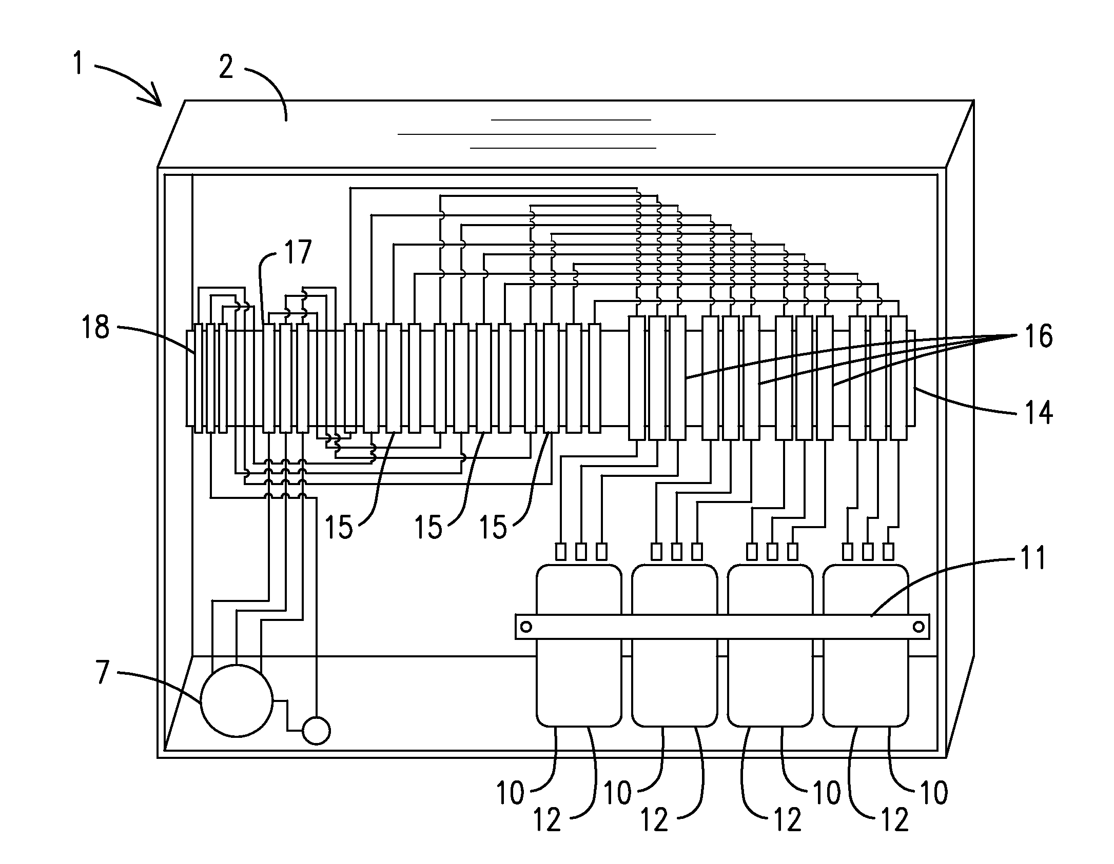
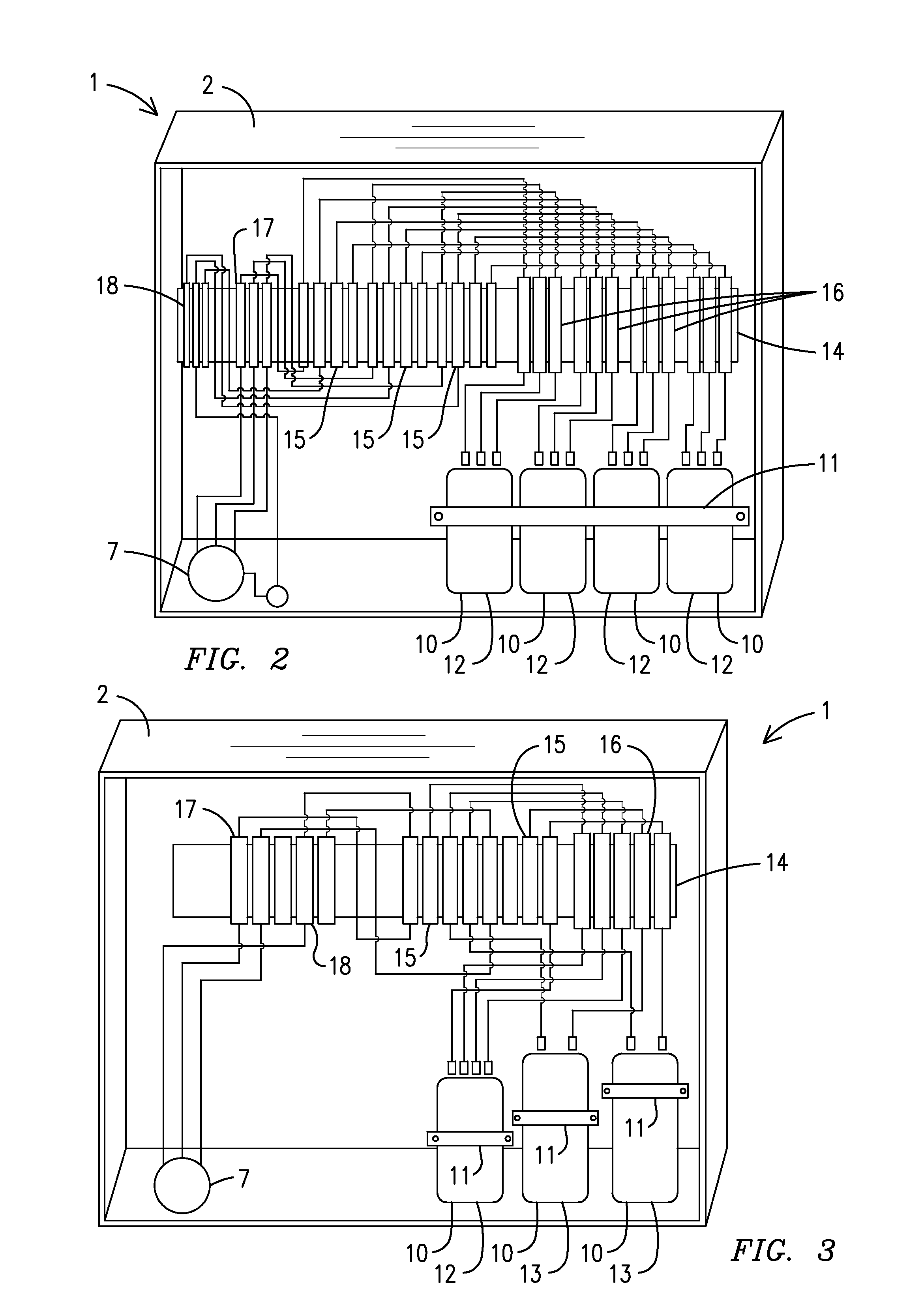
[0026]For purposes of describing the preferred embodiment, the terminology used in reference to the numbered components in the drawings is as follows:

1.device2.enclosure3.rear wall4.side wall5.front cover6.securing means7.knockout hole8.on / off status lamp9.surge arrester status lamp10.capacitor11.holding means12.variable capacitance capacitor13.fixed-value capacitor14.din rail15.terminal block16.disconnect block17.circuit breaker18.surge arrester19.bridging bar20.circuit bar21.locking means22.discreet capacitive cell23.individual tap24.common terminal

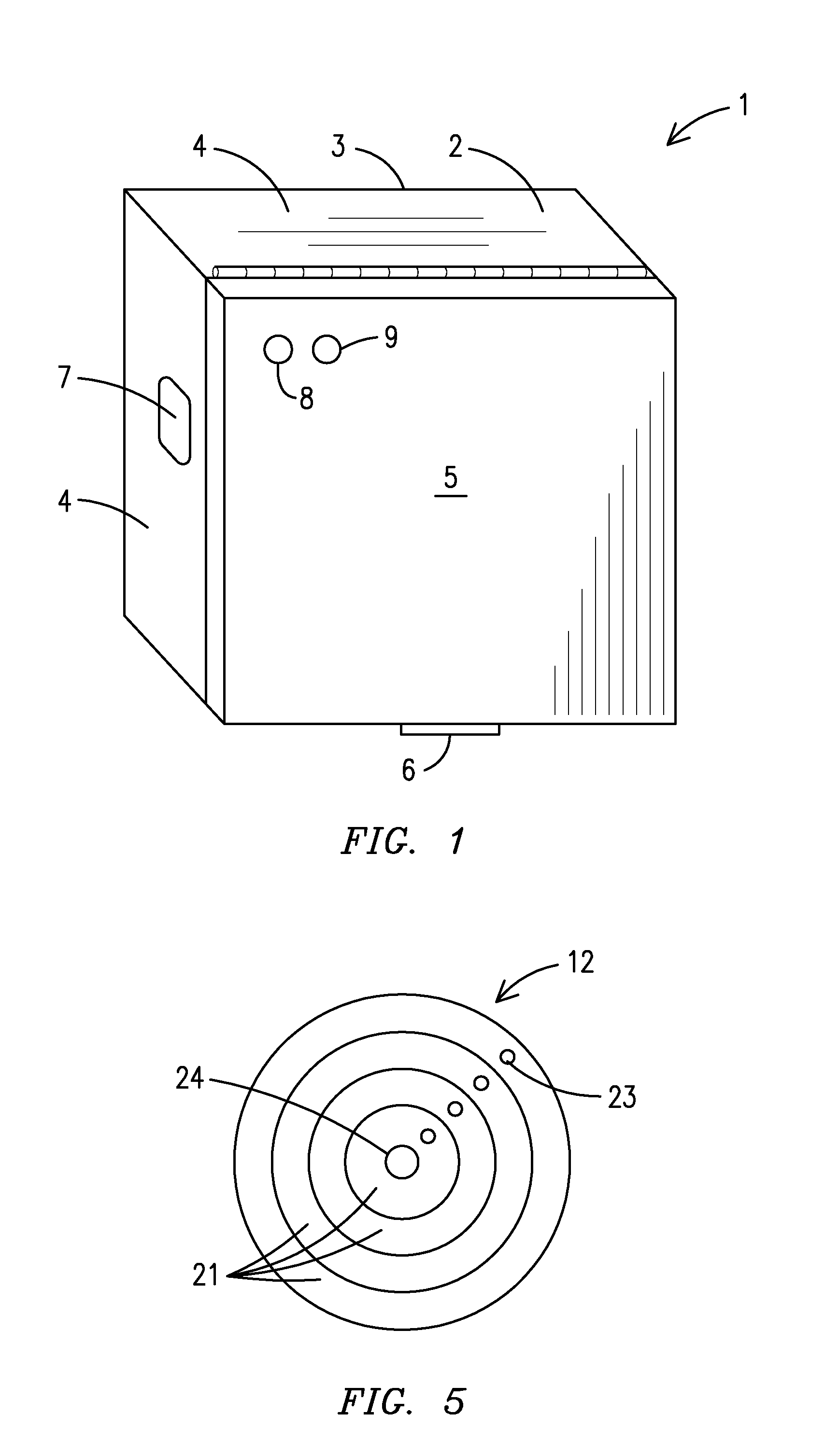
[0027]With reference to FIG. 1, a front perspective view of the outside of a power factor correction device 1 of the present invention is shown. The power factor correction device 1 preferably has an outer enclosure 2 having a rear wall 3, side walls 4, a front cover 5, a securing means 6, such as a latch, screw, etc., for securing the front cover 5 to the enclosure 2 and at least one knockout hole 7 for connecting the device to an elec...


PUM


Abstract

A power factor correction device (1) having one or more capacitors (10) in which the capacitance can be varied depending on the amount of power factor correction that is needed for a given application. Disconnect blocks (16) having internal bridging bars (19) are used to activate and deactivate fixed-value capacitors (13) and/or variable capacitance capacitors (12) within the device. The device may use variable capacitance capacitors either alone or in combination with fixed-value capacitors depending on the size of an electrical circuit. In addition to reducing electrical usage by correcting power factor, surge protection is promoted through the use of surge arresters (18).

Description

CROSS REFERENCE TO RELATED APPLICATION[0001]This application claims the benefit of U.S. Provisional Patent Application No. 61 / 168,821, filed Apr. 13, 2009. The patent application identified above is incorporated here by reference in its entirety to provide continuity of disclosure.BACKGROUND OF THE INVENTION[0002]This invention relates to energy saving devices, more particularly, an energy savings device that corrects power factor in an electrical circuit through the use of variable capacitors that may be adjusted to lower or raise the level of capacitance depending on how much or how little power factor correction is needed in a particular electrical circuit.[0003]In residential or commercial establishments, the loads served by electric utility companies are generally primarily resistive, such as a space heater, or primarily inductive, such as a motor. The inductive loads draw a combination of kilowatts (real or inductive power) and kilovars (reactive power). Capacitors are a stati...

Claims


Application Information

Patent Timeline
IPC IPC(8): G05F1/70
CPCG05F1/70
Inventor BOOTHROYD, HOWARD G.
Owner BOOTHROYD HOWARD G
Why Eureka
Try Eureka