Eureka AIR delivers breakthrough ideas for toughest innovation challenges, trusted by R&D personnel around the world.

Circuit and Methods for Temperature Insensitive Current Reference

a technology of reference current and circuit, applied in the direction of electric variable regulation, process and machine control, instruments, etc., can solve the problems of inpractical obtaining a temperature insensitive reference current from these known circuits, reference current still varies, etc., and achieves the effect of less current consumption and simple design

Inactive Publication Date: 2010-10-14
TAIWAN SEMICON MFG CO LTD
View PDF24 Cites 19 Cited by
  • Summary
  • Abstract
  • Description
  • Claims
  • Application Information

AI Technical Summary

Benefits of technology

[0013]Advantages of the use of the embodiments accrue because process elements are used to obtain the temperature compensation, so that no additional circuitry is required. Compared to prior art approaches, less current is consumed. Lower current variation means designs can be simpler.

Problems solved by technology

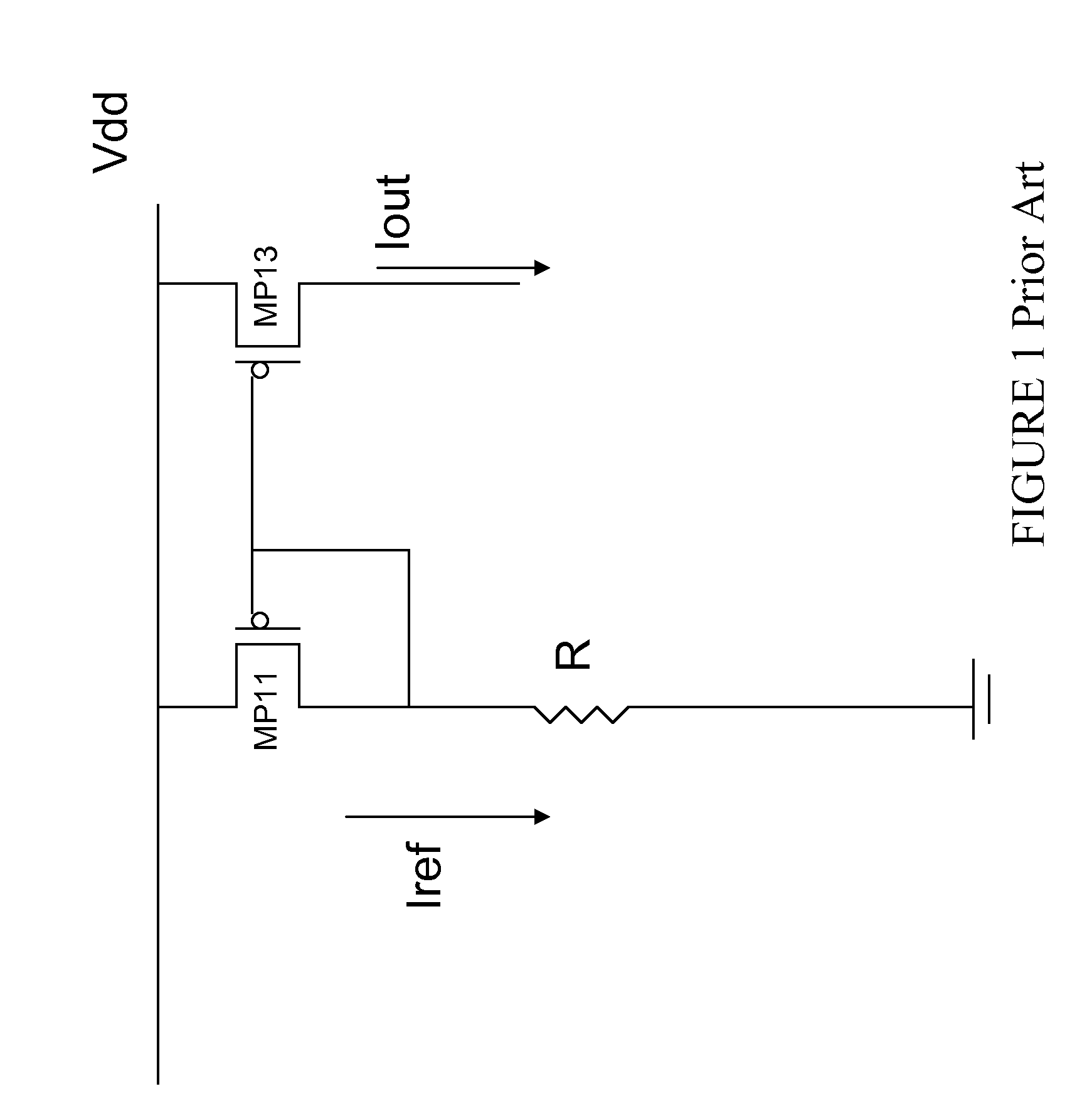
However, resistive elements of the prior art include temperature coefficients and thus create temperature dependencies, so that the resulting reference current still varies with temperature, even in a situation where the input voltage is a bandgap voltage.
Advance semiconductor process which produce smaller devices and additional process variations make obtaining a temperature insensitive reference current from these known circuits impractical.

Method used


Image

  • Circuit and Methods for Temperature Insensitive Current Reference
  • Circuit and Methods for Temperature Insensitive Current Reference
  • Circuit and Methods for Temperature Insensitive Current Reference

Examples


Embodiment Construction

[0023]The making and using of the presently preferred embodiments are discussed in detail below. It should be appreciated, however, that the present invention provides many applicable inventive concepts that can be embodied in a wide variety of specific contexts. The specific embodiments discussed are merely illustrative of specific ways to make and use the invention, and do not limit the scope of the invention.

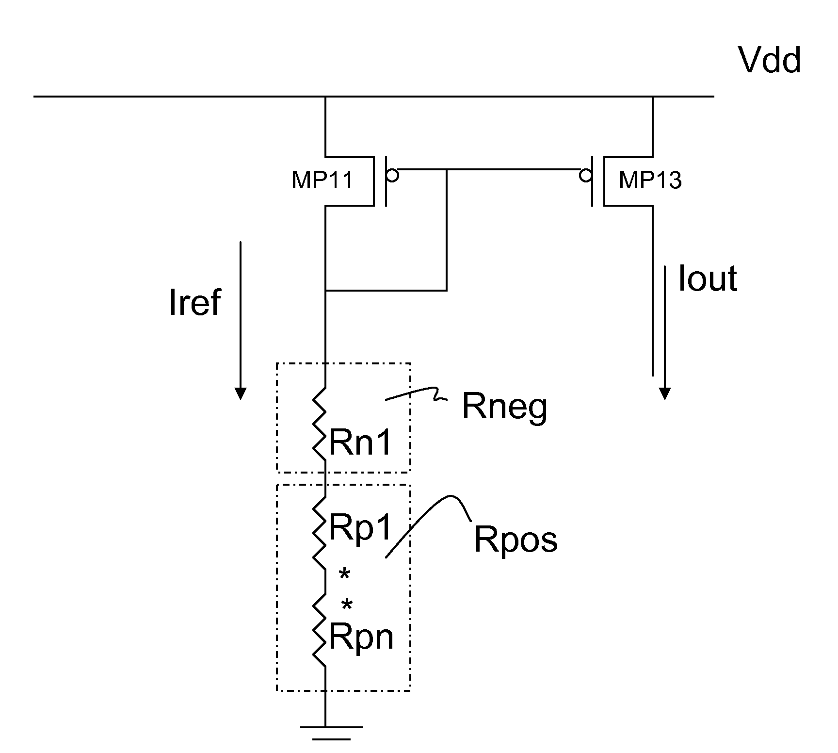
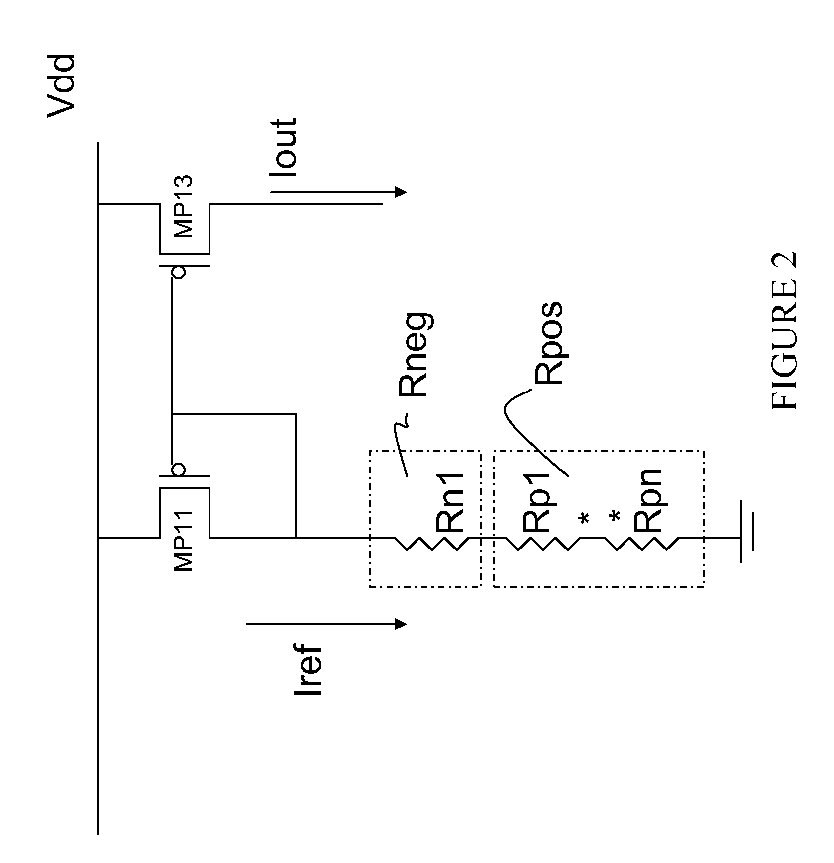
[0024]FIG. 2 depicts in one exemplary embodiment a block diagram of a temperature insensitive reference current circuit. In FIG. 2, P type MOSFET transistor MP11 is shown coupled to a positive voltage source Vdd. MP11 provides current to a resistor ladder formed of a negative temperature coefficient resistor Rneg and a positive temperature resistor Rpos. PMOS transistor MP13 is coupled with the gate and source terminals in common with MP11 and thus acts as a current mirror with MP11, producing an output current labeled Iout. Assuming the transistors MP11 and MP13 are matched ...


PUM


Abstract

Circuits and methods for providing a temperature insensitive reference current are disclosed. A voltage source is received having a temperature coefficient. A first resistive element having a positive temperature coefficient and a second resistive element having a negative temperature coefficient are series coupled to form a resistor ladder. The reference current is generated by coupling the voltage source across the resistor ladder. The temperature coefficients of the first and second resistive elements are chosen to cancel the temperature coefficient of the voltage source. In another embodiment a temperature compensated voltage source is coupled to a resistor ladder of a first resistive element and a second resistive element, and the first resistive element has a positive temperature coefficient and the second resistive element has a negative coefficient; these cancel to form a temperature insensitive reference current. A method for forming a temperature insensitive reference current from resistive elements is described.

Description

[0001]This application claims the benefit of U.S. Provisional Application No. 61 / 167,689, entitled “Circuit and Methods for Temperature Insensitive Current Reference,” filed on Apr. 8, 2009, which is incorporated herein by reference.TECHNICAL FIELD[0002]The present invention relates to a circuit and methods for providing an improved temperature compensation scheme for generating reference currents in an integrated circuit fabricated on a semiconductor substrate. The use of the invention provides advantages in circuits to produce reference currents that are independent of temperature variations.BACKGROUND[0003]A common requirement for an electronic circuit and particularly for analog or mixed signal electronic circuits manufactured as integrated circuits in semiconductor processes is a reference current, or a reference voltage. For a process variation and temperature independent voltage, prior art approaches use so called voltage “bandgap” circuits, or rely on proportional-to-absolut...

Claims


Application Information

Patent Timeline
IPC IPC(8): G05F1/10
CPCG05F3/08
Inventor LIN, CHING-TZUNG
Owner TAIWAN SEMICON MFG CO LTD
Why Eureka
Eureka Blog
Learn More