
Stereoscopic image display

a stereoscopic image and display technology, applied in the field of stereoscopic image display, can solve the problems of unnoticed accumulation of brain fat, loss of optimum binocular parallax accuracy, headache of observer, etc., and achieve the effect of long-time observation without fatigu

Inactive Publication Date: 2010-10-14
MITAKA KOHKI
View PDF5 Cites 4 Cited by
  • Summary
  • Abstract
  • Description
  • Claims
  • Application Information

AI Technical Summary

Benefits of technology

[0005]The photographing apparatus such as an operating microscope and a digital video camera forms a convergent angle by refraction of an objective lens and is set to provide an ergonomically optimum convergent angle so that the eyes of an observer may not be fatigued.
[0007]In consideration of such a related art, the present invention provides a stereoscopic image display that allows a long-time observation without fatigue.

Problems solved by technology

This involves a drawback to cause a headache for an observer when the observer observes the images for a long time in, for example, brain surgery.
If the displayed left and right images involve a slight positional deviation or a rotation, the optimum binocular parallax will lose accuracy.
To internally correct the inaccuracy, the brain unnoticeably accumulates fatigue to cause eye fatigue and a headache.

Method used


Image

  • Stereoscopic image display
  • Stereoscopic image display
  • Stereoscopic image display

Examples


Embodiment Construction

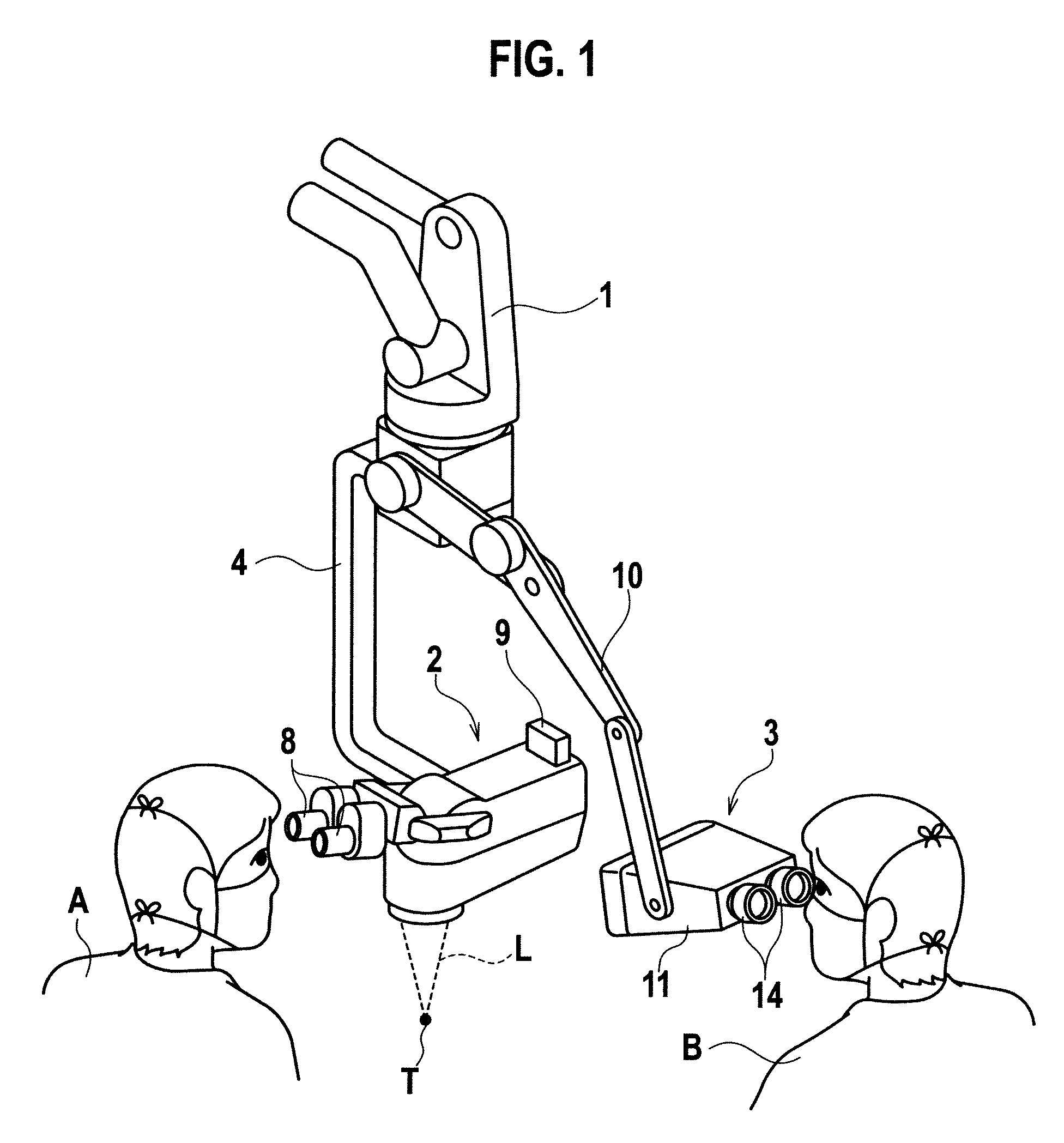
[0016]A preferred embodiment of the present invention will be explained with reference to the drawings. FIG. 1 illustrates a front link 1 of a stand apparatus (not illustrated) that supports an operating microscope 2 and a stereoscopic image display 3. The operating microscope 2 is observed by a main operator A and the stereoscopic image display 3 is observed by an assistant B.

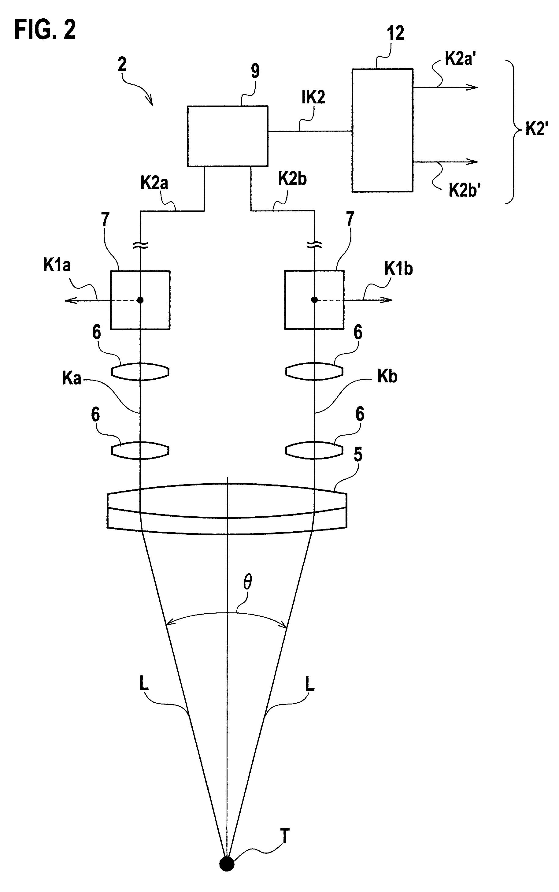
[0017]The operating microscope 2 is supported through a suspension arm 4 by the front link 1. The operating microscope 2 contains an objective lens 5, zoom lenses 6, beam splitters 7, and the like. From an operation spot T, a light beam L is guided at a predetermined convergent angle of θ to the objective lens 5, is transmitted through the objective lens 5, and is separated into two systems of optical paths Ka and Kb corresponding to left and right eyes P, respectively. The separated beams passing through the zoom lenses 6 are reflected by the beam splitters 7 toward a rear side (the back side of the plane of ...


PUM


Abstract

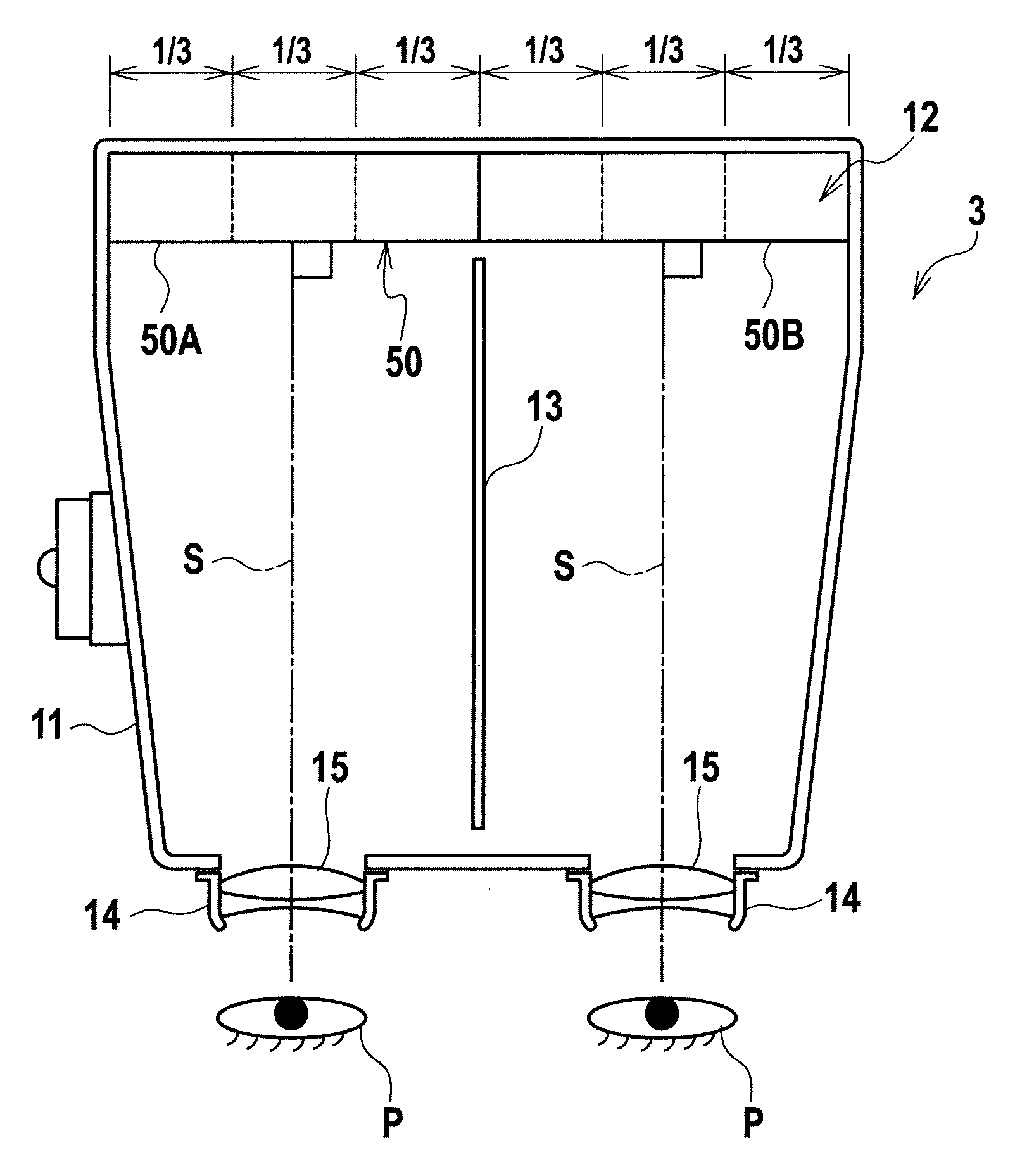
Optical axes S of eyepiece lenses 15 are parallel to each other and are perpendicular to surfaces of electronic image display panels 12. The optical axes S pass through central parts X of the electronic image display panels 12 that are main observation points of an observer, i.e., an assistant B. When observing the electronic image display panels 12, visual axes of the eyes P of the assistant will not form large angles with respect to the electronic image display panels 12, and therefore, the assistant B can stereoscopically observe electronic images displayed on the electronic image display panels12 at an original binocular parallax provided by an objective lens 5 of an operating microscope 2. As results, the assistant feels no eye fatigue or headache even when observing the images for a long time.

Description

TECHNICAL FIELD[0001]The present invention relates to a stereoscopic image display.BACKGROUND TECHNOLOGY[0002]There is a known stereoscopic image display that photographs, with a photographing apparatus such as an operating microscope and a digital video camera, left- and right-eye electronic images having binocular parallax to enable a stereoscopic view and displays the pair of left and right electronic images on a pair of left and right electronic image display panels (of liquid crystal, plasma, organic EL, or the like), respectively, so that a viewer views the electronic images through left and right eyepieces, respectively, to observe a stereoscopic image.[0003]An example of a stereoscopic image display is disclosed in Japanese Patent Publication No. 2607828. This related art employs wedge-like prisms for eyepieces to widen the left and right visual axes of an observer to a predetermined angle so that the observer may observe top-bottom-left-right center points of left and right...

Claims


Application Information

Patent Timeline
IPC IPC(8): G02B27/22
CPCA61B19/5223A61B2019/5229G02B21/22H04N13/044G02B27/026G02B27/2228G03B35/18G02B21/368A61B90/20A61B2090/372H04N13/344G02B30/34
Inventor NAKAMURA, KATSUSHIGEDOI, MASAO
Owner MITAKA KOHKI
Learn More