
Method and apparatus for fabricating a foam container with a computer controlled laser cutting device

a laser cutting device and foam container technology, applied in the direction of manufacturing tools, instruments, transportation and packaging, etc., can solve the problems of not being able to allow internal transverse cuts, conventional cutting apparatus limited by type and size, and each apparatus described present limitations in positioning foam in relation to the cutting blad

Inactive Publication Date: 2010-10-14
BATTLE FOAM
View PDF25 Cites 10 Cited by
  • Summary
  • Abstract
  • Description
  • Claims
  • Application Information

AI Technical Summary

Benefits of technology

[0006]The present invention is directed to a method of using laser cutting tools to form predetermined and custom designed text, indentations and protective compartments in a range of high density foams, thereby permitting the foam to securely hold and protect another object fit into the indentation or compartment. The method includes the use of a laser material processing system into which graphical designs and texts can be entered into a computer system and saved as templates.
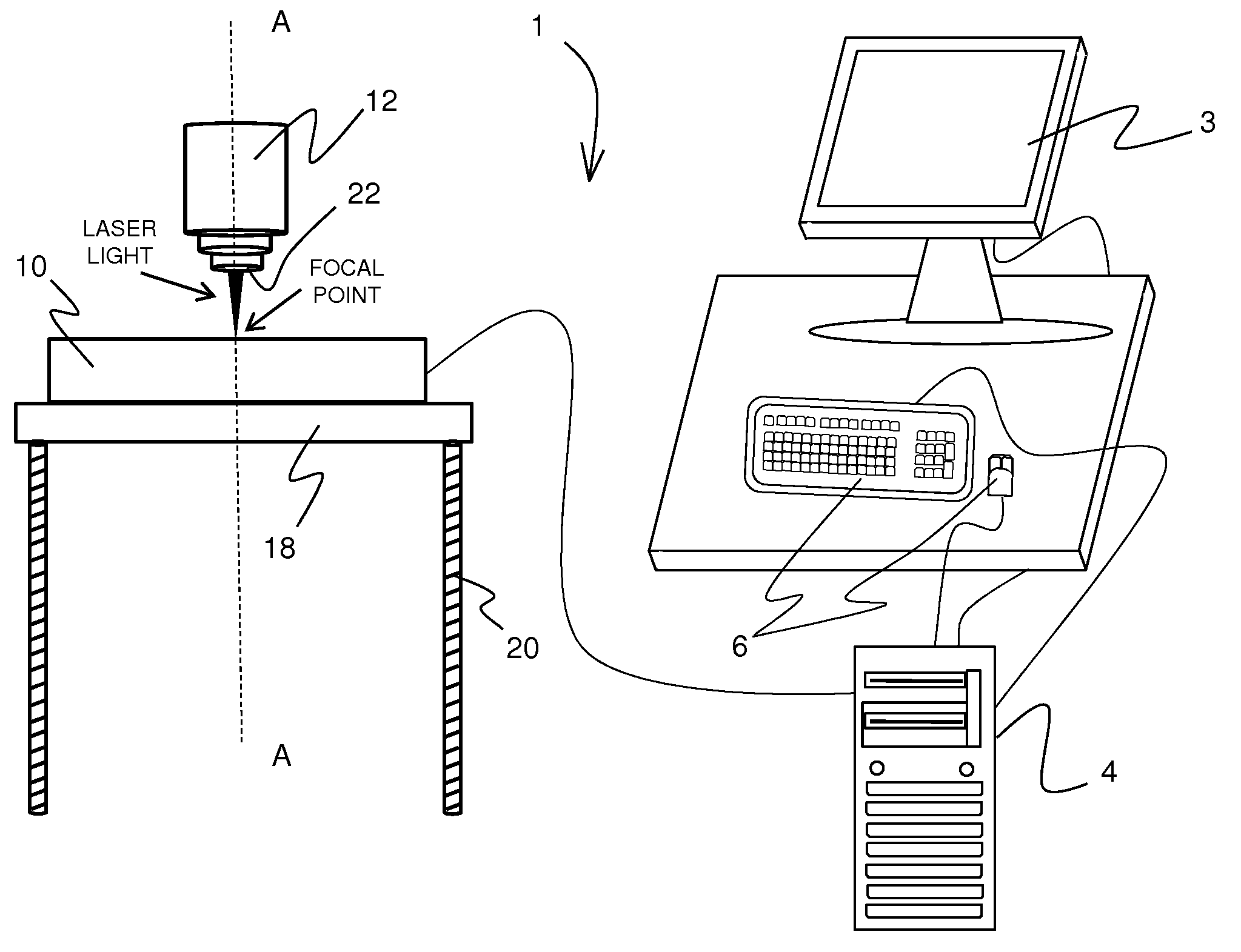
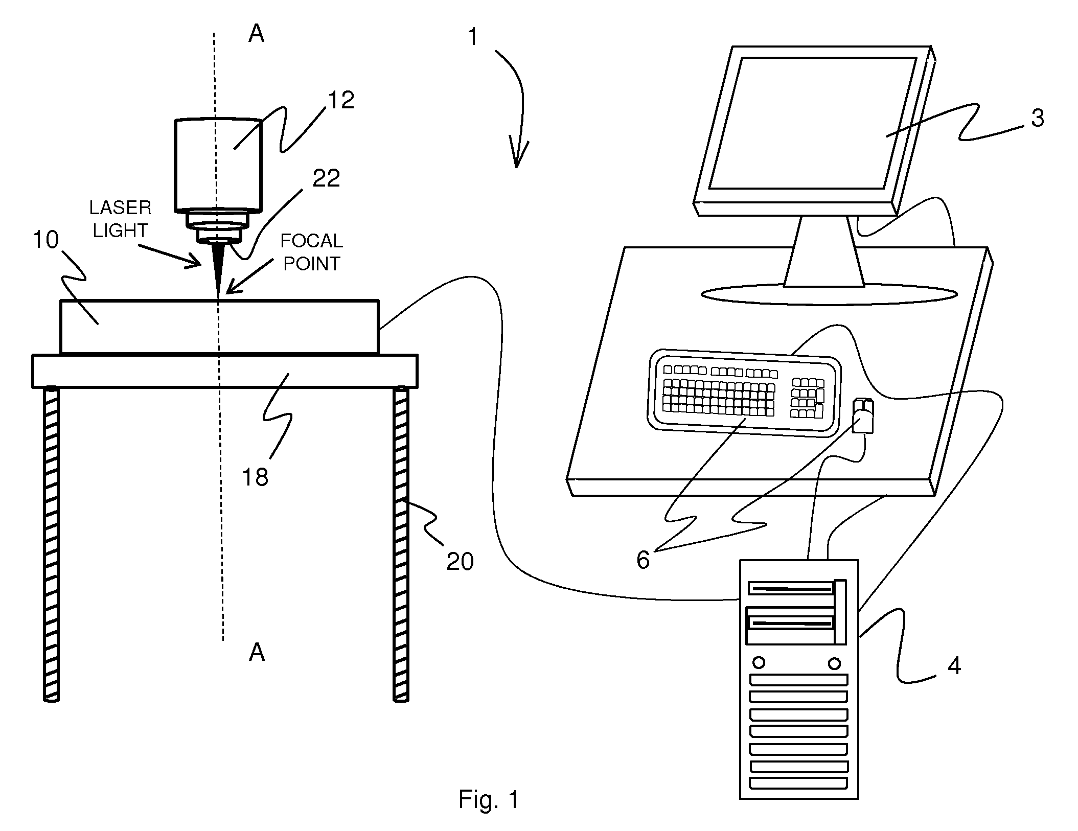
[0010]Custom design graphical indentations and text created from a design template are done by adjusting the focal point of the laser to the surface edge of the material or to a minimal depth within the material. The laser is then driven through a serious of movements in the X-direction from the first edge of the design to the furthest edge of the design and then moved in the Y-direction and then back in the X-direction to sufficiently move the laser back and forth over the design area and burn out or etch the design into the foam material. As will be described further because of the softness of the material the adjustment of speed and power are reduced to prevent overheating of the material.
[0011]In cutting through the foam material the laser focal point is adjusted to a position that focuses the laser to a depth that is beyond the thickness of the material. An appropriate lens depending upon the thickness of the material is selected and the outer edge of the beam focusing assembly of the system (the exit point of the laser from the system) is positioned directly on top of the upper surface of the foam material, thereby adjusting the final focusing lens to a focal point that is beyond the top surface of the subject material workpiece and the focal point being somewhere inside the depth of the material generally closer to a bottom surface of the workpiece rather than the top surface. Adjustments to speed and power allow the laser beam to cut through the foam material even though the focal point of the laser is not on or even close to the top surface of the foam material being cut.
[0012]In cutting the protective compartments from the custom designed template completely out of the foam material an appropriate enclosure must be formed with a specific profile to hold the selected objects. The present invention uses a high density foam backing of a thickness dependent upon the size and weight of the selected objects. This foam backing is adhered to the cutout foam material using a hot roller glue system that coats adhesive to each irregular surface of the cutout foam material and securely adheres the foam backing to the foam material further protecting the selected objects within the protective compartments.

Problems solved by technology

Each of the apparatus described present limitations in positioning the foam in relation to the cutting blade.
Notably, these conventional cutting apparatus are limited by the type and size of the cutting blade and do not allow internal transverse cuts into the foam to create three dimensional compartments.
Rollers or die cutters have the limitation of high costs to create the molds for each unique pattern indentation thus limiting the ability to create custom designed compartments that would fit oddly shaped objects.
This method also presents the limitation of positioning the foam along the electrically heated wires and allows for only straight cuts through the foam not transverse cuts to form indentations and compartments.
High density foam is a petroleum based product and particularly flammable.
When used with high energy lasers the material is highly susceptible to overheating and catching fire.
Any smoke and debris from such overheating or fire will damage the laser system as well as at the very least coat the lens and mirrors of the focusing assembly system causing cracking and destruction of these elements.

Method used


Image

  • Method and apparatus for fabricating a foam container with a computer controlled laser cutting device
  • Method and apparatus for fabricating a foam container with a computer controlled laser cutting device
  • Method and apparatus for fabricating a foam container with a computer controlled laser cutting device

Examples


Embodiment Construction

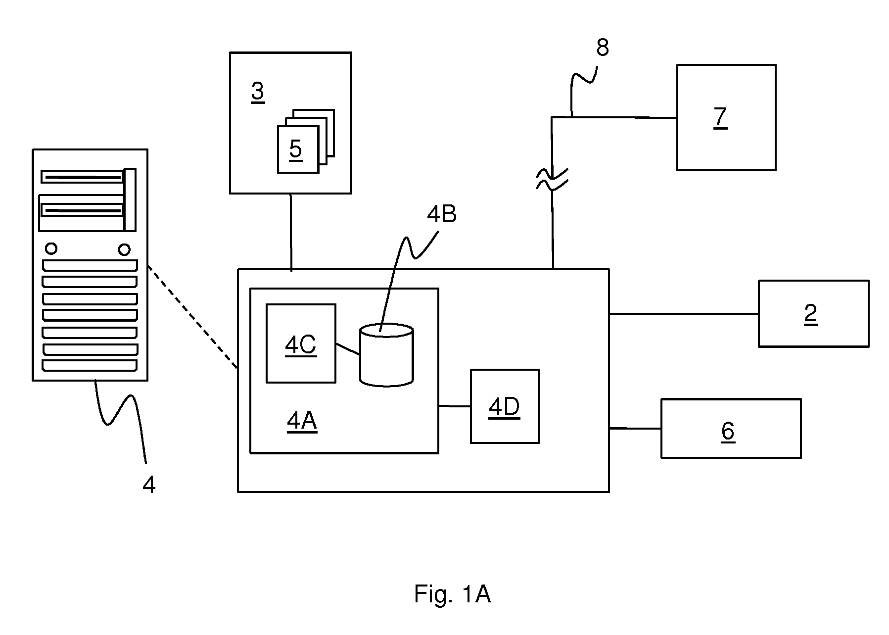
[0029]As described briefly above, the present invention is directed to an apparatus and method of fabricating foam containers or packaging with custom text, indentations and specifically profiled protective compartments using a computer system and software controlled laser cutting device for transferring a predetermined template through the computer system and via the laser cutting device cutting a foam material to replicate the predetermined template. As shown in FIGS. 1 and 1A, the exemplary computer and software controlled laser material processing system 1 includes, for example, an image capture device 2 such as a digital camera or a digital scanner which can input an image of a template or design to be stored in the computer memory of the computer system. The system 1 includes a display screen 3, an electronics and memory unit 4 connected to display screen 3 for storing and displaying one or more template images 5 through display screen 3, and a local control input 6 connected ...


PUM

PropertyMeasurementUnit
Thicknessaaaaaaaaaa
Densityaaaaaaaaaa
Shapeaaaaaaaaaa

Abstract

A method and apparatus for fabricating a foam container by using a laser cutting apparatus to precisely cut and remove portions of foam in order to form custom and predetermined text, indentations and protective compartments in the foam, and more particularly a method of controlling the laser relative to high density foam to create precise cuts completely through the foam without subsequently adjusting the focal point of the laser, the cuts being made according to exterior dimensions of an object to be supported and protected in the high density foam.

Description

FIELD OF THE INVENTION[0001]The present invention relates to a method and apparatus for fabricating a foam container by using a laser cutting apparatus to precisely cut and remove portions of foam in order to form custom and predetermined text, indentations and protective compartments in the foam, and more particularly a method of controlling the laser relative to high density foam to create precise cuts completely through the foam without subsequently adjusting the focal point of the laser, the cuts being made according to exterior dimensions of an object to be supported and protected in the high density foam.BACKGROUND OF THE INVENTION[0002]The fabrication of foam containers with compartmental cutouts is well known. Methods using machinery that have movable working benches to position and move the foam along a cutting blade that may be positioned on a vertical or horizontal axis in relation to the table have been widely used and are described in U.S. Pat. No. 6,386,083, U.S. Pat. ...

Claims


Application Information

Patent Timeline
IPC IPC(8): B32B3/26G06F17/50
CPCB23K26/046Y10T428/24736B23K26/4065B23K2103/42B23K2103/50Y10T428/249953B23K26/40
Inventor FILIP, ROMEO
Owner BATTLE FOAM
Learn More