Valve integrated prosthetic expulsion pump

a valve and prosthetic technology, applied in the field of valve assembly for use with a prosthetic limb socket, can solve the problems of unable to expel all of the air from within the socket, affecting the mobility of the prosthesis, and affecting the mobility of the residual limb,

Active Publication Date: 2010-10-14
ALPS SOUTH EURO
View PDF3 Cites 33 Cited by
  • Summary
  • Abstract
  • Description
  • Claims
  • Application Information

AI Technical Summary

Benefits of technology

[0013]It is an object of the present invention to provide an air expulsion pumping system for a prosthetic socket that is easy to manufacture.
[0014]It is a further object of the present invention to provide an air expulsion pumping system for a prosthetic socket that is easy to install in a prosthetic socket without the use of any physical fasteners.
[0015]It is a further object of the present invention to provide an air expulsion pumping system for a prosthetic socket that is easily replaceable without destroying the prosthetic socket.
[0019]In the above preferred embodiment, the distal end of prosthetic socket has a curved interior surface from which the inside surfaces of the well extend. The pump housing, when fitted within the well, having an upper surface congruent with the curvature of the interior surface of the socket to define a smooth interior curvature at the distal end of the prosthetic socket. When the prosthetic socket is used with an elastomeric liner or sheath, the smooth interior curvature at the distal end of the prosthetic socket together with the liner or sheath provides a comfortable fit of the residual limb within the socket. The elastomeric spring member is selected based on the degree of vacuum deemed appropriate for each individual patient. As the patient donns the prosthesis, air will be forced out of the socket through the central passageway. After the prosthetic is donned and the patient ambulates, any air remaining between the residual limb and socket, or between the liner or sheath and socket, will be suctioned out through the central passageway via the action of the expulsion pump providing continuous total contact between the residual limb and the socket.

Problems solved by technology

One of the limitations encountered with this type of prosthetic assembly is that the weight of the prosthesis is carried mostly by the distal part of the residual limb.
Another limitation is due to the location of the relief valve not being at the most distal point of the socket.
As the residual limb with or without a liner or sheath is extended within the socket past the valve, the valve becomes blocked by the residual limb and thus fails to expel all of the air from within the socket.
Furthermore, it is well known that when an amputee dons a prosthesis and begins taking the pressures of transmitting the weight of the body through the surface area of the residual limb to the bone, there is increased pressure on the residual limb which causes the eventual loss of fluids within the residual limb.
This loss of fluids causes the volume of the residual limb to decrease during the day.
Because of such pressures on the residual limb resulting in volume changes thereof, pistoning during ambulation of the residual limb within the socket occurs since the prosthesis does not fit well at all times.
Although this valving system operates efficiently, the manufacture and assembly thereof is quite complicated since it includes several intricately molded parts some of which are made of metal.
Thus, from the above examples of the prior art systems, some of the drawbacks are noise and weight related to the use of metal components in the pump body, packaging limitations due to the geometry of the pumps, which affect the cosmetic appearance of the prosthesis, the need for batteries or other power sources, and the need for pistons and cylinders to pump air out of the socket.

Method used


Image

  • Valve integrated prosthetic expulsion pump
  • Valve integrated prosthetic expulsion pump
  • Valve integrated prosthetic expulsion pump

Examples


Embodiment Construction

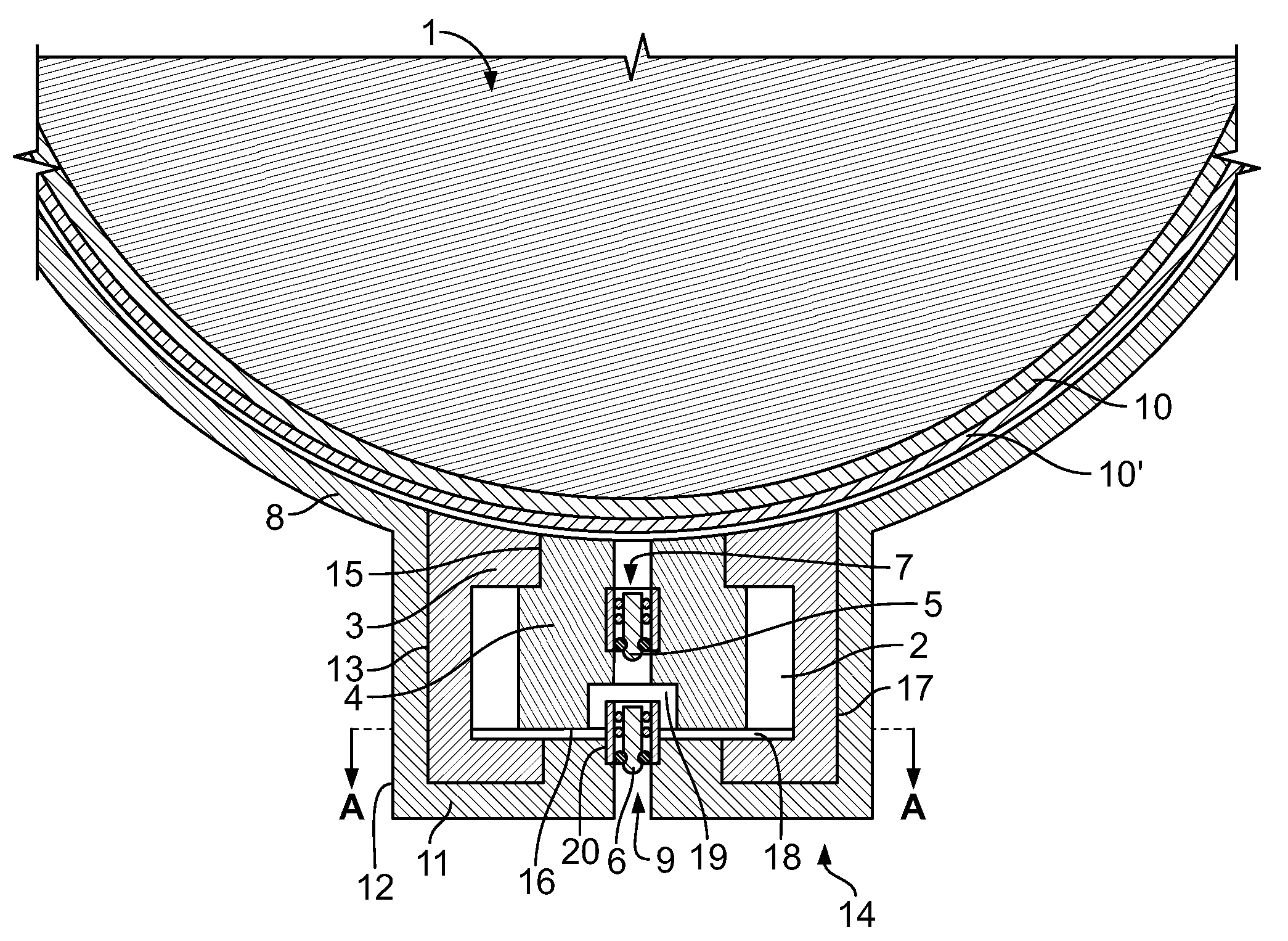
[0024]As shown in FIG. 1, a residual limb 1 of a patient is fitted with an elastomeric liner or sheath 10 having an exterior fabric surface 10′ and inserted into a prosthetic socket 8. The air expulsion pumping system 14 is shown mounted within the distal end of the prosthetic socket. The prosthetic socket 8 may be constructed of a substantially rigid material such as polyester or acrylic resin or thermoset plastics including polypropylene and polyethylene, or any other appropriate materials. One example illustrating the manufacture of a prior art prosthetic socket is disclosed in U.S. Pat. No. 5,571,208 to Caspers, which is incorporated herein by reference. It is noted that this is the typical prosthetic system having an air expulsion valve 112 that the present invention improves upon. The socket of the present invention could be worn with a liner donned over the residual limb of the patient such as liner 90 in the system disclosed in U.S. Pat. No. 5,571,208, or with a liner 10 hav...


PUM


Abstract

An air expulsion pump for a prosthetic socket adapted to be worn on a residual limb of an amputee. The pump includes an elastomeric housing which fits snugly in a well defined in the lower end of the socket. The pump is easy to install by simply sliding it into the well. The pump has an upper surface commensurate with the inside surface of the socket in that both surface have the same radius of curvature. The pump includes an elastomeric spring member and two check valves that together with the elastomeric housing exert a continuous vacuum within the prosthetic socket. When donned by the user, the pump provides continuous total contact between the socket and the residual limb of the user as the user ambulates.

Description

CROSS-REFERENCE TO RELATED APPLICATION[0001]This is a continuation-in-part of provisional application No. 61 / 212,389 filed Apr. 10, 2009.BACKGROUND OF THE INVENTION[0002]The present invention relates generally to prosthetic devices and, more particularly, to a valve assembly for use with a prosthetic limb socket.[0003]A prosthesis is often used to replace an amputated portion of a limb and to help restore the amputee's ability to use that limb. A prosthesis for a lower extremity amputation will often include an artificial foot connected to an upright assembly (pylon, tube or shaft) which is in turn connected to a custom fitted socket assembly.[0004]Prior art prosthetic assemblies generally require an inner liner or sheath generally comprising a flexible, thermoplastic material conforming to the residual limb of the amputee, and a more rigid, thermoplastic outer socket which is attached to the upright assembly of the prosthetic assembly. The outer socket may or may not be used with t...

Claims


Application Information

Patent Timeline
Patent Type & Authority Applications(United States)
IPC IPC(8): A61F2/80
CPCA61F2002/805A61F2/80
Inventor LAGHI, ALDO A.
Owner ALPS SOUTH EURO
Why Eureka
Try Eureka