
No-drill rear sight scope mount base

a technology of scope and mount base, which is applied in the direction of scaffolding, machine supports, curtain suspension devices, etc., can solve the problems of the scope flexing on recoil, and achieve the effect of preventing minor upward recoil forces and any loss of accuracy

Inactive Publication Date: 2010-10-21
SPINELLI MICHAEL ANGELO
View PDF13 Cites 24 Cited by
  • Summary
  • Abstract
  • Description
  • Claims
  • Application Information

AI Technical Summary

Benefits of technology

[0016]The present invention is easy to manufacture. It consists of few components, all of which are fairly easy to machine. This keeps costs down and makes the invention affordable.
[0018]The scope mount body accepts long eye relief scopes, which are an advantage in hunting as there is no scope ocular close to your eye blocking the line of sight, thus providing excellent field of view when acquiring the target.
[0019]The receiver end of the rifle is also left uncluttered by this scope mount body design, leaving this area open for easy access to the operating bolt and ammunition magazine.
[0024]A top body mounted compression screw threaded hole is provided so that a headless compression screw may be utilized against the forward top edge of the releasable second part of a two part base. This is to prevent minor upward recoil forces from jarring the front of the releasable second part up from the first part of two piece sight base variants.
[0025]Prototypes of this invention have shown the design and applications to be quite sound and without failure for over six hundred test firings without any lose of accuracy.

Problems solved by technology

Such a long span between fasteners probably caused scope flexing on recoil.

Method used


Image

  • No-drill rear sight scope mount base
  • No-drill rear sight scope mount base
  • No-drill rear sight scope mount base

Examples


Embodiment Construction

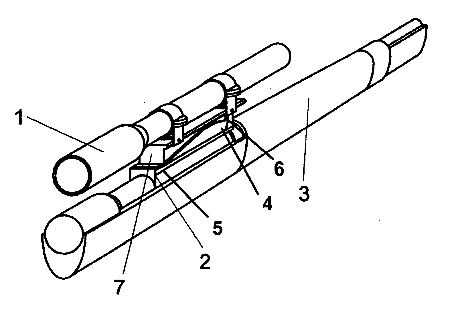
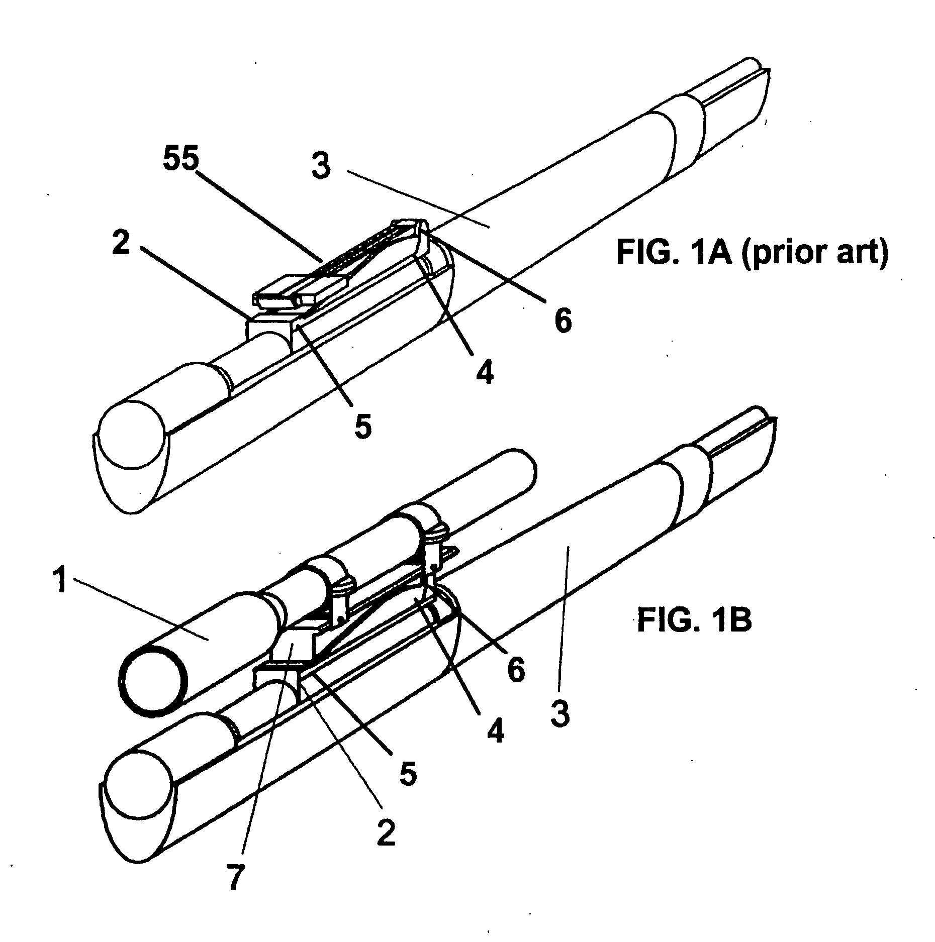
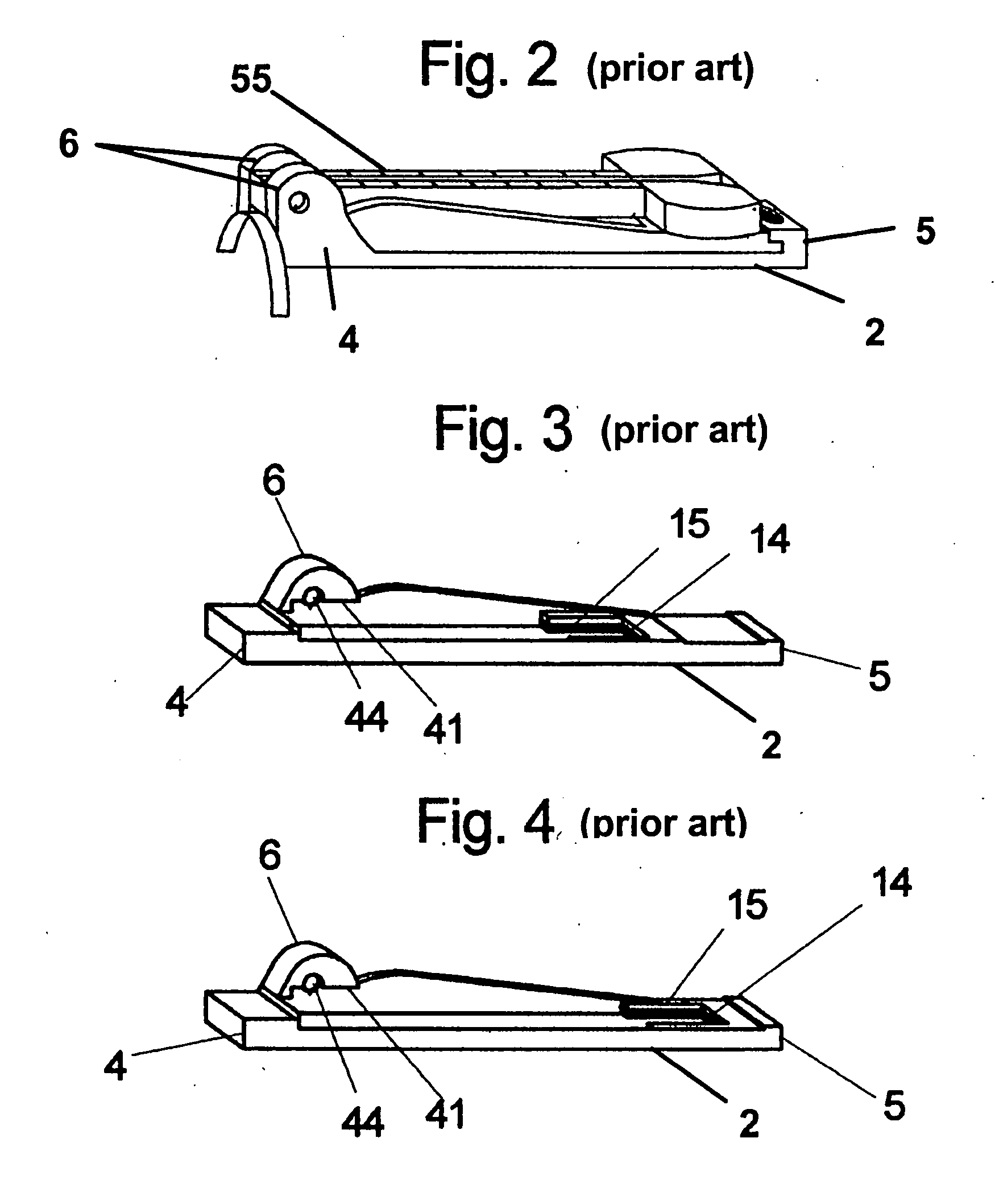
[0043]The success of my rear sight long eye relief scope mount is dependent on the preexistence of certain specific features in the host Mauser 98 (FIG. 1) long tangent rear sight base (FIG. 2);[0044]A—In the anterior portion (4), a pair of inwardly projecting, opposing, bosses (6) that project upwards on the sight base. There is also a boss through hole (44) in each of these said bosses (6). These through holes are positioned so that their upper circumference and horizontal diameter passes through the bosses' (6) lower side edge (42).[0045]B—In the posterior (5) of the sight base, a pair of opposing spring slots (15) is located longitudinally to the bore (36) in the sight base posterior.

[0046]The scope mount body (7) consists of top (10), bottom (11), side (12), front (8), and back (9). On the top of the body, you have the general configuration to accept the telescopic sight (54). The top back (10) also has three vertical screw holes. These three holes are central to the lateral bo...


PUM


Abstract

A scope mount base design which readily accepts onto a preexisting rear sight base without any alteration of the sight base except for the easy removal of the original sight leaf and mainspring. This scope mount invention achieves solid lockup by the use of the appropriate sized threaded support fixtures and scope mount configuration to successfully engage these rear sight slots that originally contained the sight leaf and mainspring, and thus achieve strong lockup of the scope mount to the sight base.

Description

I. RELATED APPLICATION[0001]This application is a continuation in part of application, filed on May 8, 2006, and titled “NO DRILL REAR SIGHT SCOPE MOUNT BASE”, by Michael Angelo Spinelli, inventor. The provisions of that application are incorporated by reference as if set out in full herein.II. BACKGROUND OF THE INVENTION[0002]A. Field of the Invention[0003]The Invention relates to a telescopic sight mount for a rifle, specifically a telescopic sight mount for a '98 Mauser rifle.[0004]B. Description of the Related Art[0005]Many rifle designs especially those of military nature were built with quite robust rear sight designs, most famous of these being the K98 Mauser. Over the years many other rifle designs have emulated those of the Mauser. My invention is concerned with the manner in which the K98 Mauser long tangent rear sight base assembly was configured, in particular the top portion of the rear sight base. This base design allowed for the easy removal of the sight blade (55) at...

Claims


Application Information

Patent Timeline
IPC IPC(8): F41G1/387
CPCF41G11/003F41G1/387
Inventor SPINELLI, MICHAEL ANGELO
Owner SPINELLI MICHAEL ANGELO
Learn More