
Automatic door closing hinge and double swing door structure

a door closing and hinge technology, applied in the direction of hinges, wing accessories, manufacturing tools, etc., can solve the problems of not being able to install on double swing doors which are opened inward and outward, and achieve the effect of enhancing the function of the door closing operation by the action of the air cushion, simplifying the manufacturing process, and improving the service li

Inactive Publication Date: 2010-10-21
SAWA CORP +1
View PDF18 Cites 9 Cited by
  • Summary
  • Abstract
  • Description
  • Claims
  • Application Information

AI Technical Summary

Benefits of technology

[0003]Incidentally, the automatic door closing hinge configured to absorb a shock with the air damper has superior features such that a smooth shock absorption is achieved without contaminating the periphery with oil leakage and so on. However, the automatic door closing hinge described above is configured to be used for outward-opening or inward-opening doors, that is, for one-side opening doors, and cannot be installed on double swing doors which are opened inward and outward. Therefore, the automatic door closing hinge configured to absorb a shock with the air damper which can be installed on the double swing doors which can be opened inward and outward is being called for.
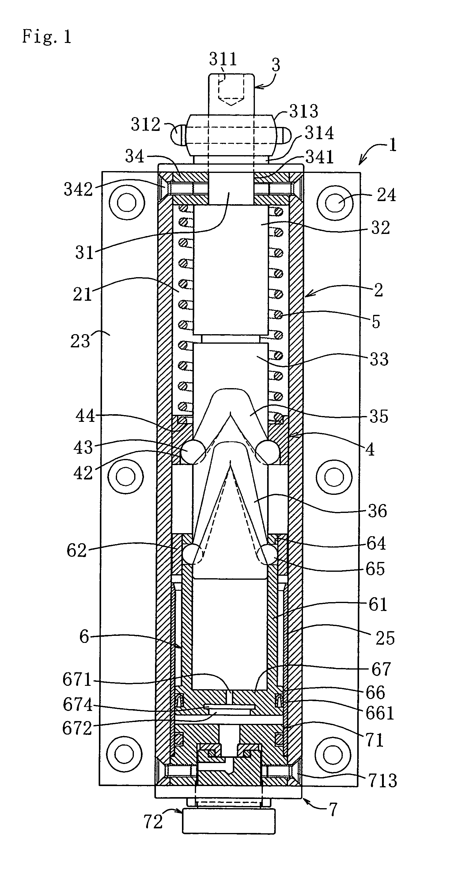
[0009]The automatic door closing hinge according to the present invention is characterized in that an air distribution hole is provided on a bottom portion of the piston, the air distribution hole includes a large diameter portion on the other end side of the cylinder, a small diameter portion on the one end side, and a valve plate between the large diameter portion and the small diameter portion, the valve plate is capable of forming a gap communicating from one end side to the other end side between the large diameter portion and the valve plate and closing the small diameter portion, and an adjustable screw portion being capable of adjusting the size of the air flow channel formed between a male thread and a female thread by the strength of screwing is provided at the other end of the cylinder.
[0012]In addition, by forming the respective first and second cam grooves of the substantially V-shape continuously in the circular shape, the manufacturing process is simplified.
[0013]Also, by forming the difference of elevation between the upper and lower ends of the second cam groove to be longer than that of the first cam groove, the capacity of the air trap is increased, so that the shock-absorbing function of the door-closing operation by the action of the air cushion can be enhanced.
[0014]Also, by configuring the valve plate of the air distribution hole on the bottom portion of the piston so as to form the gap communicating from one end side to the other end side between the large diameter portion and the valve plate and be capable of closing the small diameter portion and, in addition, by providing the adjustable screw portion which is capable of adjusting the size of the air flow channel by the strength of the screwing, smooth opening operation when opening the door is secured, and the action of the air cushion can be adjusted to an adequate degree easily, and the stabilization of the degree of the action of the air cushion is achieved.

Problems solved by technology

However, the automatic door closing hinge described above is configured to be used for outward-opening or inward-opening doors, that is, for one-side opening doors, and cannot be installed on double swing doors which are opened inward and outward.

Method used


Image

  • Automatic door closing hinge and double swing door structure
  • Automatic door closing hinge and double swing door structure
  • Automatic door closing hinge and double swing door structure

Examples


Embodiment Construction

[0016]Referring now to the drawings, an embodiment of the present invention will be described.

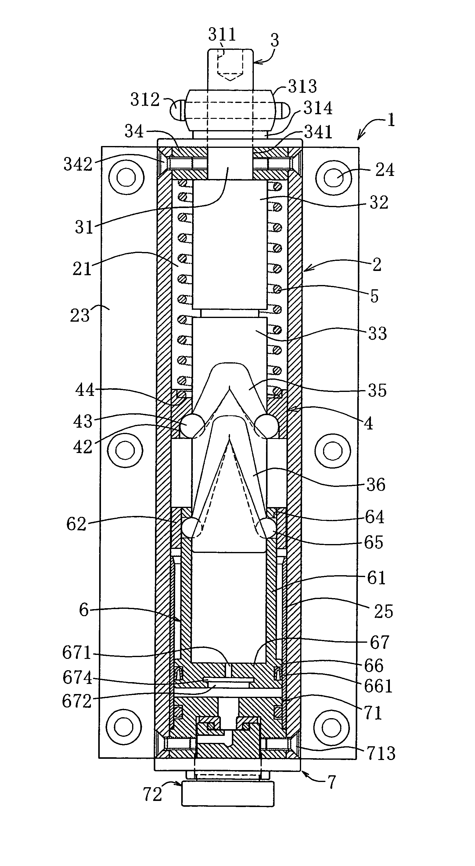
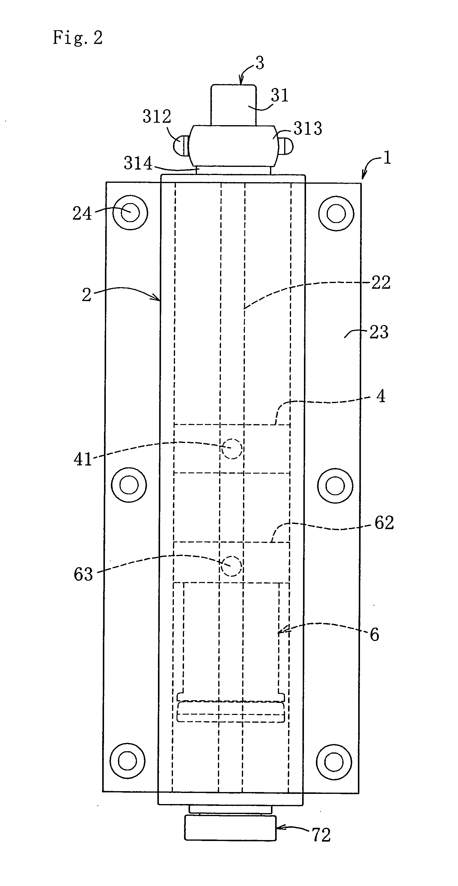
[0017]An automatic door closing hinge 1 according to this embodiment includes a cylinder 2, an operating rod 3 rotatably attached to the cylinder 2 so as to project partly outward from an upper end side of the cylinder 2, a compression ring 4 formed into a short cylindrical shape arranged on an outer periphery of the operating rod and inside the cylinder 2, a compression coil spring 5 arranged on an upper side of the compression ring 4 and inside the cylinder 2, a piston 6 arranged on a lower side of the compression ring 4 inside the cylinder 2, and an air adjusting portion 7 provided on a lower end side of the cylinder 2, as shown in FIG. 1 to FIG. 5.

[0018]The cylinder 2 has a hollow portion 21 of a substantially cylindrical shape, and is formed with a depressed groove 22 at front and rear positions of the interior surface thereof so as to extend respectively in the vertical direction. A r...


PUM


Abstract

An automatic door closing hinge configured to absorb a shock by an air damper which can be installed on a double swing door opening inward and outward and a double swing door structure provided with the automatic door closing hinge are provided. An automatic door closing hinge 1 is configured in such a manner that balls 43 are engaged with a cam groove 35 formed on an outer peripheral surface of an operating rod in a cylinder 2 at opposed positions so as to have a substantially V-shape continuing in a circular shape at opposed positions thereof, the balls 43 are engaged with a compression ring 4 urged downward by a restraining force of a compression coil spring 5, the movement of the balls 43 with respect to the cam groove 35 is in conjunction with the vertical movement of the compression ring 4, balls 65 are engaged with a cam groove 36 being formed under the cam groove 35 and having substantially the same shape as the cam groove 35 at opposed positions thereof, the balls 65 are engaged with the piston 6, the movement of the balls 65 with respect to the cam groove 36 is in conjunction with the vertical movement of the piston 6, and air on the lower side of the piston 6 in the cylinder 2 is gradually flowed out according to the downward movement of the piston 6.

Description

TECHNICAL FIELD[0001]The present invention relates to an automatic door closing hinge having a shock-absorbing function achieved by an air damper and a double swing door structure having the automatic door closing hinge.BACKGROUND ART[0002]In the related art, an automatic door closing hinge configured to rotate an opened door in a closing direction automatically using a restoring force of a coil spring and provided with a shock-absorbing function for absorbing a shock applied when the door is closed using a hydraulic cylinder is known and, in recent years, an automatic door closing hinge configured to absorb a shock with an air damper instead of the hydraulic cylinder is proposed. The automatic door closing hinge includes a type, for example, configured in such a manner that a piston is stored and arranged in a cylinder provided on one of a pair of vanes, and an operating rod which is fixed at an upper portion to the other vane is arranged within the cylinder, balls disposed so as t...

Claims


Application Information

Patent Timeline
Patent Type & Authority Applications(United States)
IPC IPC(8): E05F1/12E05F3/20E05F3/02E05D7/086
CPCE05D3/08E05F1/1223E05F3/02E05F3/20E05Y2900/132Y10T16/5393E05Y2201/696Y10T16/53984Y10T16/304Y10T16/2771Y10T16/283E05Y2201/638E05D15/54
Inventor SAWA
Owner SAWA CORP
Learn More