Device for surface masking

a technology for masking surfaces and devices, applied in the direction of spraying apparatus, liquid surface applicator, coating, etc., can solve the problems of large installation time and effort, large effort and effort, and the majority of masking materials are not usable for protection of another surface, etc., to achieve the effect of reducing length, extending masking area coverage, and reducing thickness

Inactive Publication Date: 2010-10-21
CEDAR RIDGE RES
View PDF5 Cites 9 Cited by
  • Summary
  • Abstract
  • Description
  • Claims
  • Application Information

AI Technical Summary

Benefits of technology

[0016]In a further embodiment, a long masking panel has perforations thereby allowing individual paint panels of desired lengths to be produced by separating perforations. In a similar arrangement, long masking panels have folds enabling their length to be reduced while packaged. These two approaches can be combined such that panel portions can be folded at perforation lines allowing individual portions to be used separately, or allowing two or more panel portions to be unfolded and used together without tearing the perforation lines between the panel portions. Alternatively, a long masking panel can be folded and then later unfolded and torn or cut to achieve a desired length.
[0017]In an embodiment, masking panels are designed such that a portion of a panel along the masking edge has a lesser thickness than the remainder of the panel providing a region for a strip covering an adhesive such that the thickness of that portion, the adhesive, and the covering strip have a total thickness that substantially equals the remainder of the panel. This arrangement enables packaging where the stack of panels is not biased towards one side. Moreover, the thicker portion of the panel not having the covered adhesive provides additional control to the user due to its additional rigidness. Under a similar arrangement, a masking tape can be attached along an edge of a more rigid protective material such that a portion of the tape is able to be used for achieving a masking seal.
[0018]In an embodiment, a masking panel has adhesive on at least one side of its top surface and adhesive on at least one opposing side its bottom surface. The adhesive on the bottom surface is used to provide a masking edge along a surface to be painted. The adhesive on the top surface is used to provide an attachment edge for attaching the masking panel to additional protective material in order to extend masking area coverage. After the masking panel has been installed alongside a surface to be painted, a second masking material, such as plastic sheeting, can then be attached to the adhesive on the top surface of the masking panel so as to extend the masking surface area, for example to protect an entire floor.

Problems solved by technology

Much of what can be a time consuming effort can be spent attempting to achieve a straight edge between the surface to be painted and the surface being masked because the tape doesn't have sufficient rigidity to maintain a desired masking edge.
Considerable time is usually required to apply (or install) the masking materials (tape, newspaper, etc.) and, after paint has been applied and dried, the masking materials are for the most part not usable for protection of another surface.
In another typical scenario, considerable time is often spent placing masking tape around each window pane in a window before painting or staining the window.
As with the previous scenario, considerable time and effort is required to install the masking materials, the installed masking materials are typically unusable for protecting additional surfaces, and a large quantity of masking materials are required to protect surfaces.

Method used


Image

  • Device for surface masking
  • Device for surface masking
  • Device for surface masking

Examples


Embodiment Construction

[0038]The present invention will now be described more fully in detail with reference to the accompanying drawings, in which the preferred embodiments of the invention are shown. This invention should not, however, be construed as limited to the embodiments set forth herein; rather, they are provided so that this disclosure will be thorough and complete and will fully convey the scope of the invention to those skilled in the art. Like numbers refer to like elements throughout.

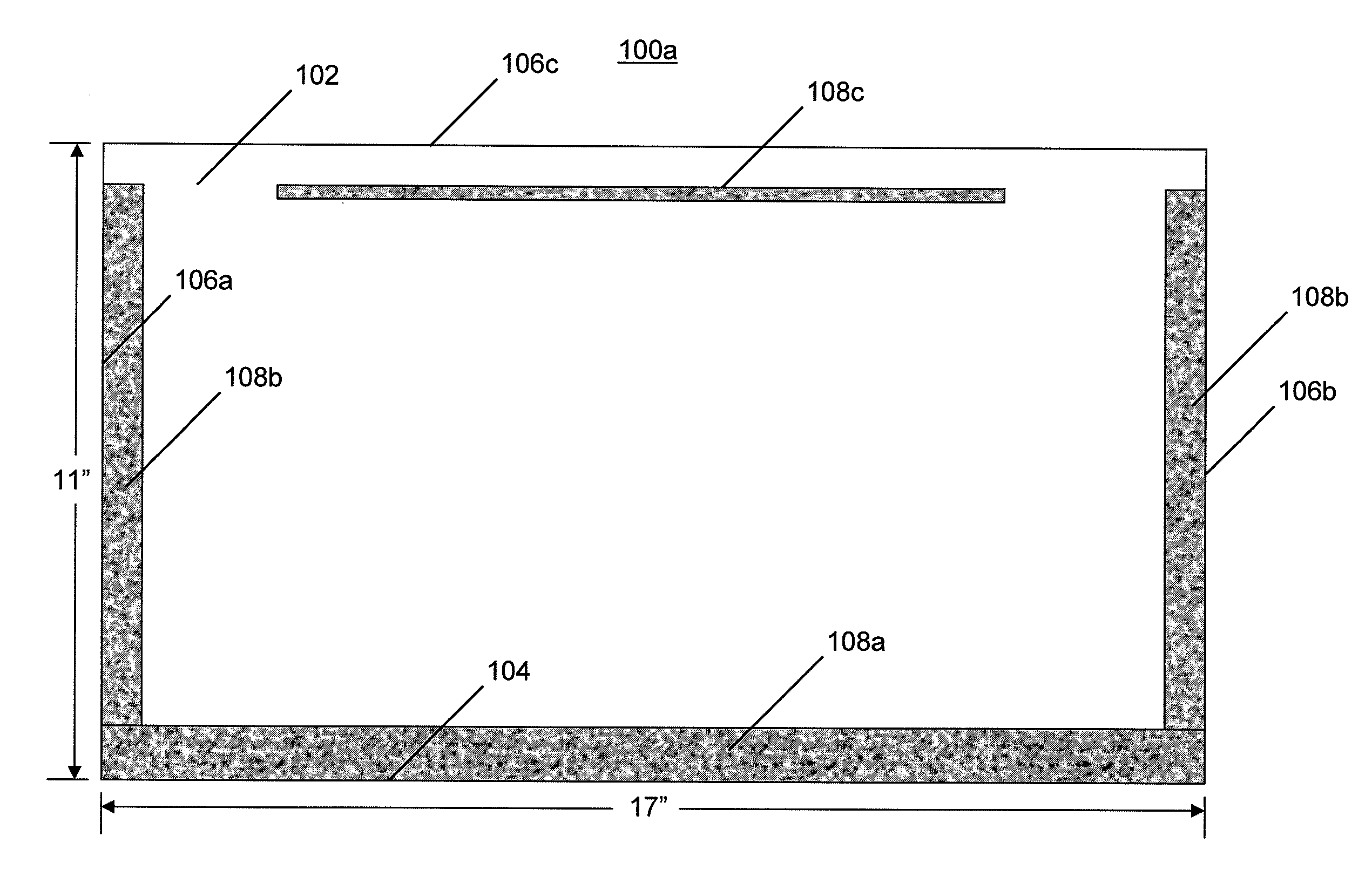
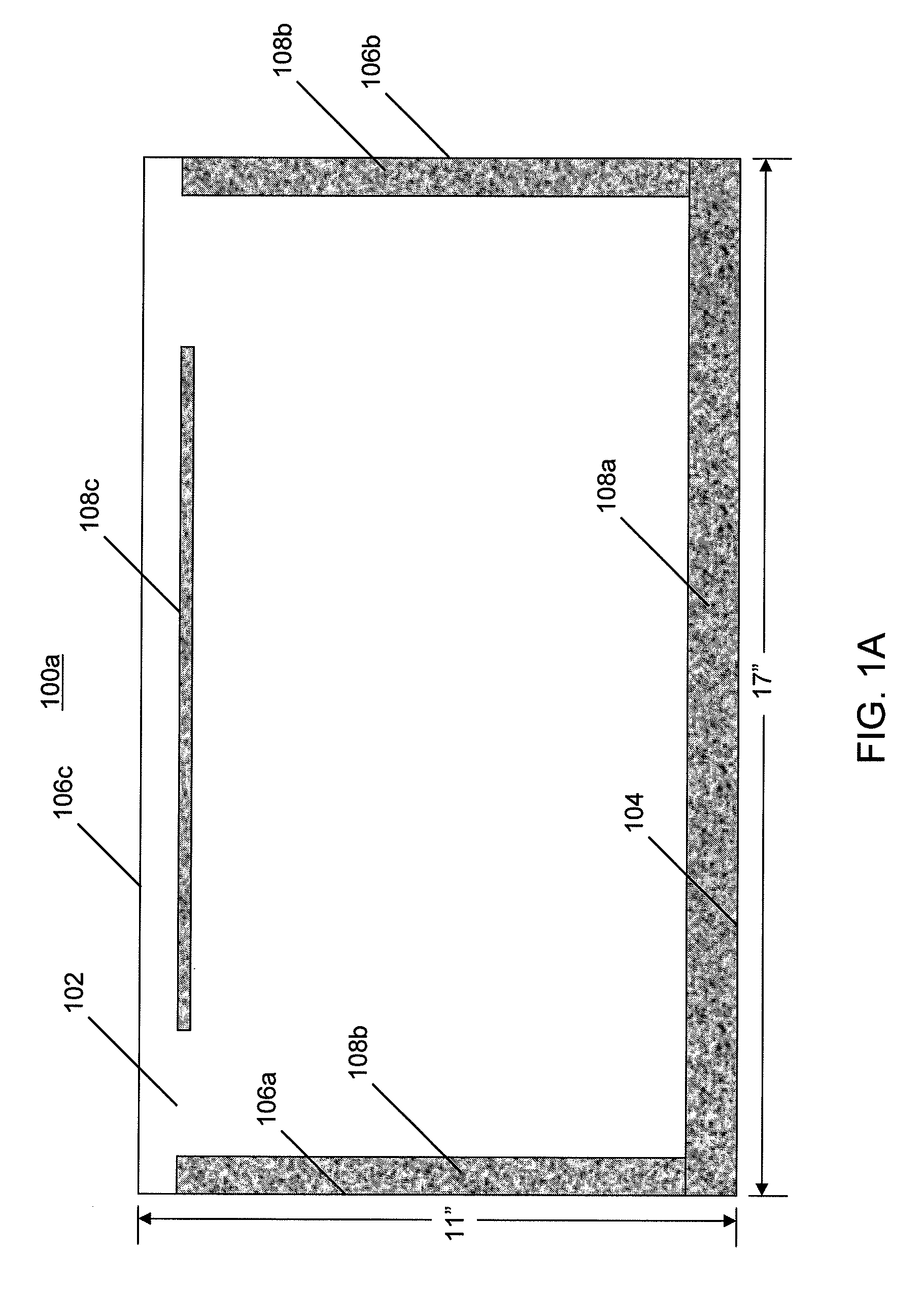
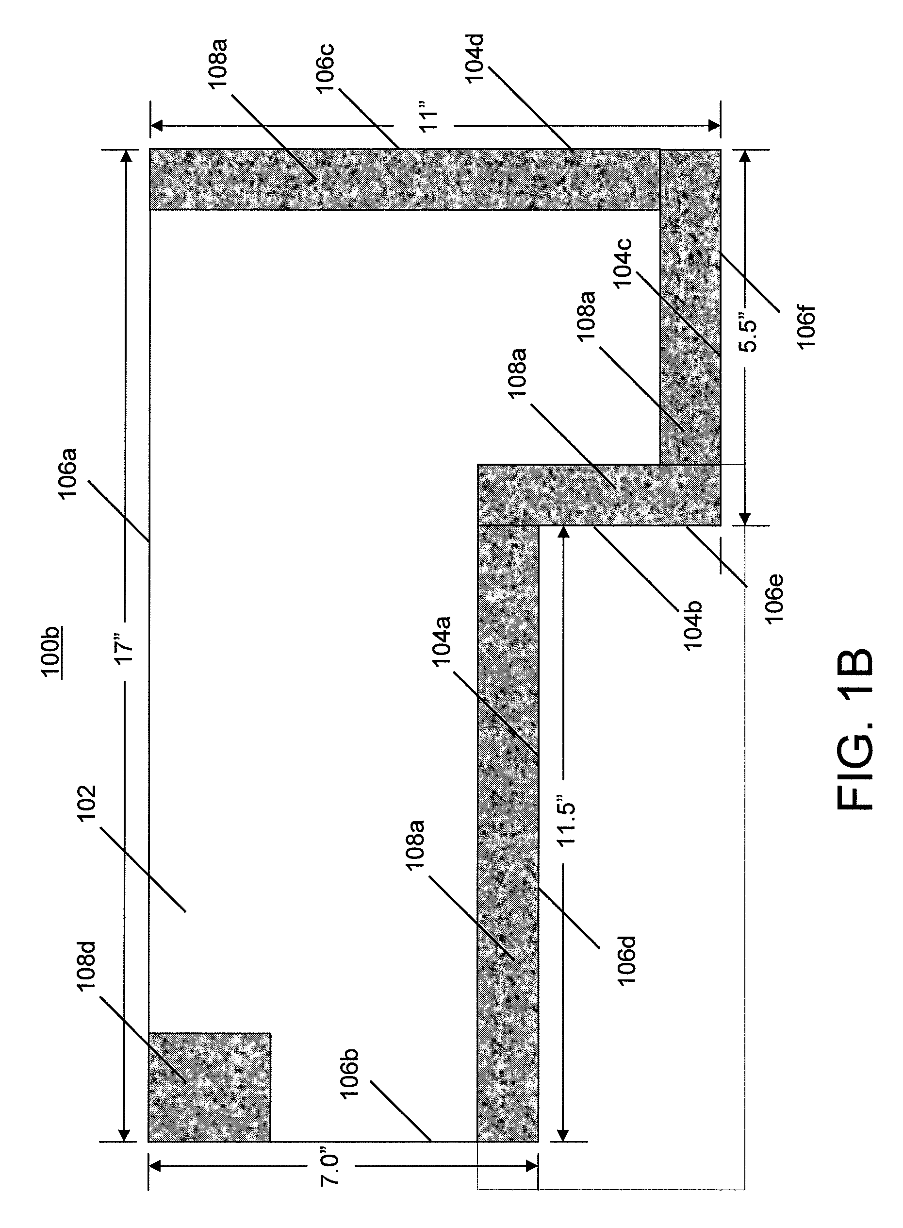
[0039]The present invention provides an improved system and method for surface masking involving a masking panel having at least one masking edge pre-fabricated to have a masking shape that substantially matches a desired masking boundary between a non-protected surface intended to have a substance (e.g., paint) applied to it and an adjacent protected surface intended to be masked so the substance will not be applied to it. The masking panel has sufficient rigidity to maintain the masking edge shape during inst...


PUM


Abstract

A masking panel to cover a protected first surface, such as a wall surface, floor surface, ceiling surface, door surface, door frame, fire place surface, window, window frame, window pane, decorative molding, chair rail or baseboard, while paint, stain, sealant or other chemicals is applied to an adjacent second surface. The masking panel includes a reusable protective material to be placed over at least a portion of the protected first surface. The reusable protective material includes at least one masking edge to create a masking boundary between the protected first surface and the adjacent second surface where the at least one masking edge has a masking edge shape that is pre-fabricated to substantially match the masking boundary. The masking panel additionally includes an adhesive fixed on the reusable protective material in the direction of the protected first surface along the at least one masking edge and at least one of the one or more holding edges to secure the reusable protective material to the protected first surface.

Description

BACKGROUND OF THE INVENTION[0001]Conventional systems and methods for masking surfaces such as wall, glass, brick, or the like typically involve use of a masking tape, which is typically one to two inches wide but can be bought in wider sizes, for example, five to six inches wide. Typically, the user of masking tape must carefully unroll the tape while pressing it against a surface to be painted (or stained or otherwise have a chemical or other substance applied) in order to protect an adjacent surface. Much of what can be a time consuming effort can be spent attempting to achieve a straight edge between the surface to be painted and the surface being masked because the tape doesn't have sufficient rigidity to maintain a desired masking edge. Similar to masking tape, masking paper comes in a roll and therefore requires unrolling the paper and having to carefully hold the paper so that it doesn't coil while pressing it against the wall. Generally, masking tape and masking paper are v...

Claims


Application Information

Patent Timeline
Patent Type & Authority Applications(United States)
IPC IPC(8): B05C11/00
CPCB05B15/045B05B12/20
Inventor DEMPSTER, CYNTHIA K.ROBERTS, MARK D.FULLERTON, LARRY W.
Owner CEDAR RIDGE RES
Why Eureka
Try Eureka