Nearly Index-Matched Luminescent Glass-Phosphor Composites For Photonic Applications

a technology of phosphor-converting leds and luminescent glass, which is applied in the direction of discharge tube luminescnet screens, discharge tubes/lamp details, semiconductor lasers, etc., can solve the problems of inefficient extraction of phosphor-converted light, wavelength conversion suffers from phosphor conversion loss, and devices have deficiencies

Inactive Publication Date: 2010-10-21
QUARKSTAR
View PDF7 Cites 74 Cited by
  • Summary
  • Abstract
  • Description
  • Claims
  • Application Information

AI Technical Summary

Benefits of technology

[0013]The glassy material can be an optical glass comprising an amount from 5% to about 35% of SiO2; an amount from about 55% to about 88% of PbO; optionally an amount le

Problems solved by technology

Each of these conventional methods and devices has deficiencies.
Wavelength conversion suffers from phosphor conversion loss and package designs that do not extract phosphor-converted light efficiently.
When the phosphor is in direct contact with the LED source, the phosphor suffers from optical losses by reflection of phosphor-emission back into the LED source rather than through the optic and out of the LED.
Scattering then reduces efficiency by increasing the path length (a) inside the phosphor layer by trapping of the emissions by total internal reflection and (b) inside the dev

Method used


Image

  • Nearly Index-Matched Luminescent Glass-Phosphor Composites For Photonic Applications
  • Nearly Index-Matched Luminescent Glass-Phosphor Composites For Photonic Applications
  • Nearly Index-Matched Luminescent Glass-Phosphor Composites For Photonic Applications

Examples


example 1

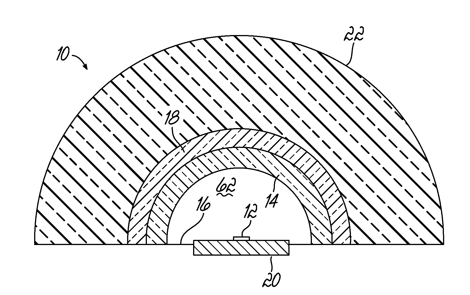
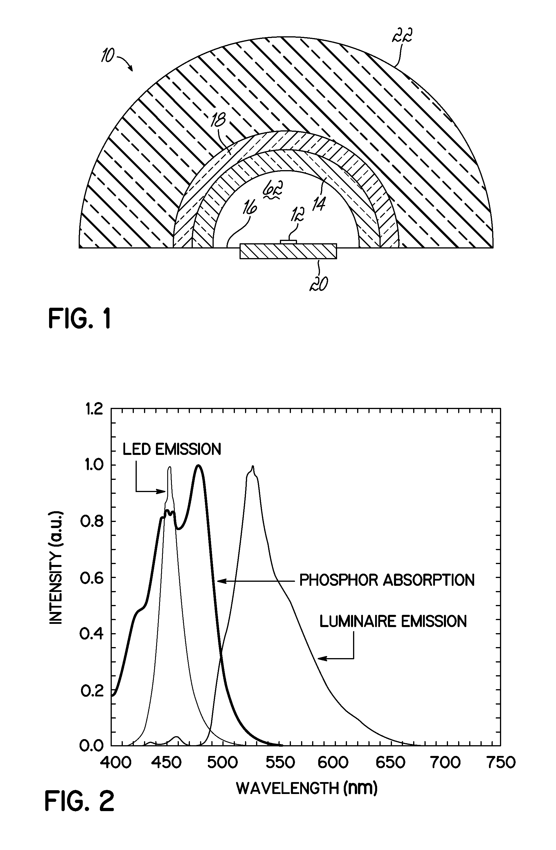
[0058]The efficiency of the ELIXIR LED 10 according to the present invention is demonstrated with a computer simulation of a ray tracing diagram, shown in FIG. 9. Herein, the ELIXIR LED 10 is constructed as described above with a phosphor radius, r, and equal to 1.9 cm.

[0059]The ray tracing diagram illustrates the various paths the phosphor-emitting photons can take in exiting the ELIXIR LED 10. Ray 1 exits the ELIXIR LED 10 without encountering any reflections and comprises approximately 35% of the phosphor-emissions. Ray 2 (representing approximately 35% of the phosphor-emission) demonstrates one particular benefit of the ELIXIR LED 10. Ray 2 is emitted in a direction toward the planar reflector 16, where substantial emissions loss occurs in a conventional pcLED package design. However, in the ELIXIR LED 10, the phosphor emission is reflected at the phosphor-air interface 112. Ray 2 can then exit the ELIXIR LED 10 and may avoid the planar reflector 16 entirely. Ray 3, comprising a...


PUM

PropertyMeasurementUnit
Fractionaaaaaaaaaa
Fractionaaaaaaaaaa
Fractionaaaaaaaaaa

Abstract

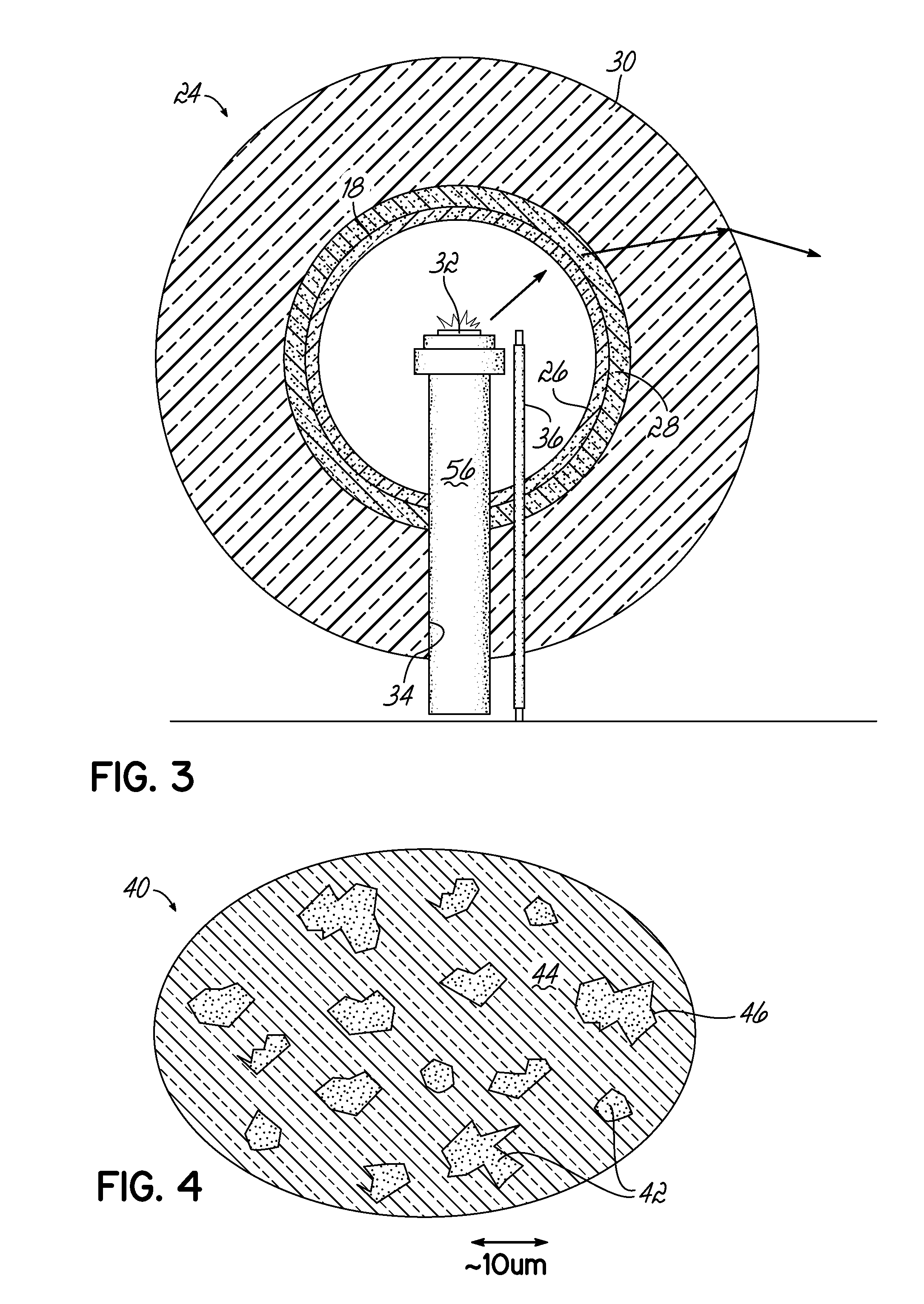
A light emitting composite material (40) comprising a glassy material (44) and a phosphor (14) suspended in the glassy material (44), wherein the refractive index of the phosphor (14) is approximately equal to the refractive index of the glass material. The light emitting composite material (40) can be used in phosphor-containing light emitting devices, solid-state laser (64) diodes, and as a luminescence collector (90).

Description

CROSS-REFERENCE TO RELATED APPLICATIONS[0001]This application claims the benefit of U.S. Provisional Application No. 60 / 961,185, filed Jul. 19, 2007, which is hereby incorporated by reference herein in its entirety.TECHNICAL FIELD[0002]The present invention relates generally to the field of solid-state lighting and more specifically to high efficiency phosphor-converted LEDs.BACKGROUND[0003]Solid-state lighting (SSL) is a type of lighting that does not use an electrical filament or a gas in the production of light. A primary advantage of SSL over conventional lighting technologies is the potential engery savings as a result of its higher luminous efficencies over conventional lighting devices. For example, SSL is capable of 50% efficiency with 200 lumen per watt (lm / W) efficacy (compared to 15 lm / W for incandescents and 60-90 lm / W for fluorescents) and up to 100 khr lifetimes. This is approximately 100 times the lifetime of conventional incandescent bulbs and 10 times the lifetime o...

Claims


Application Information

Patent Timeline
IPC IPC(8): H01L31/0232H01L33/50H01L33/44H01J1/62C09K11/08C09K11/56C09K11/67C09K11/54H01L33/54
CPCC09K11/02H01L33/501H01L33/505C03C2214/16C09K11/7774H01S5/0092C03C14/006H01L33/54H01S5/0087H01S5/02257
Inventor ALLEN, STEVEN C.STECKL, ANDREW J.
Owner QUARKSTAR
Why Eureka
Try Eureka