
Light emitting device and electronic device using the same

a technology of infrared light and electronic devices, which is applied in the direction of electroluminescent light sources, chemistry apparatuses and processes, and light sources of color, can solve the problems of weak intensities of conventional infrared leds, narrow light emitting wavelength ranges, etc., and achieve the effect of effective infrared light and high intensity

Inactive Publication Date: 2010-10-21
EVERLIGHT ELECTRONICS
View PDF5 Cites 6 Cited by
  • Summary
  • Abstract
  • Description
  • Claims
  • Application Information

AI Technical Summary

Benefits of technology

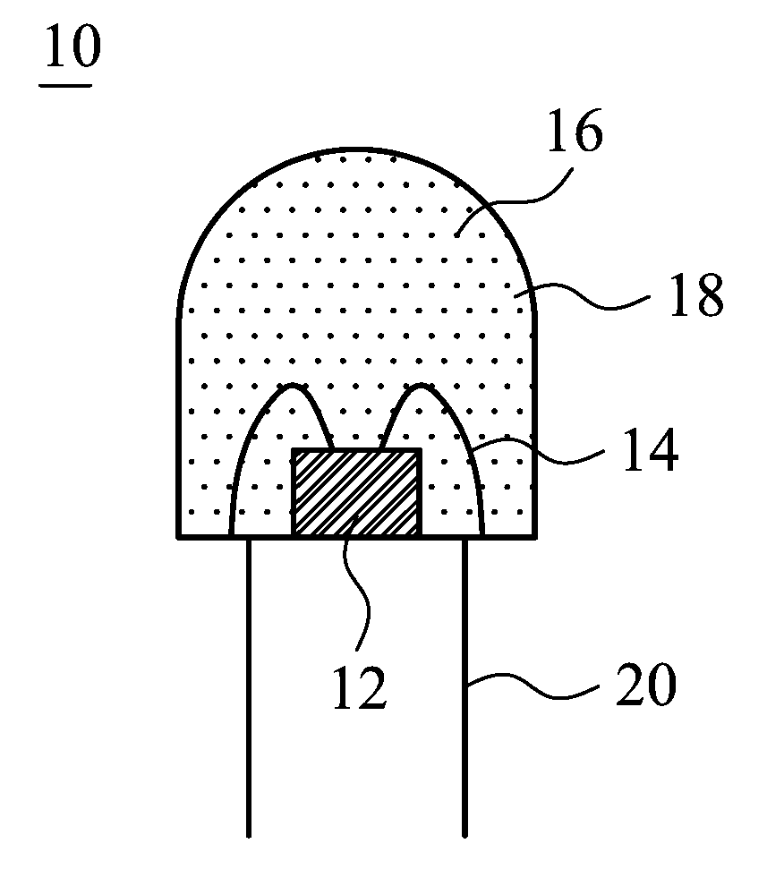
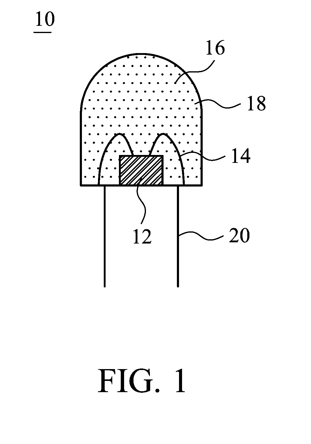
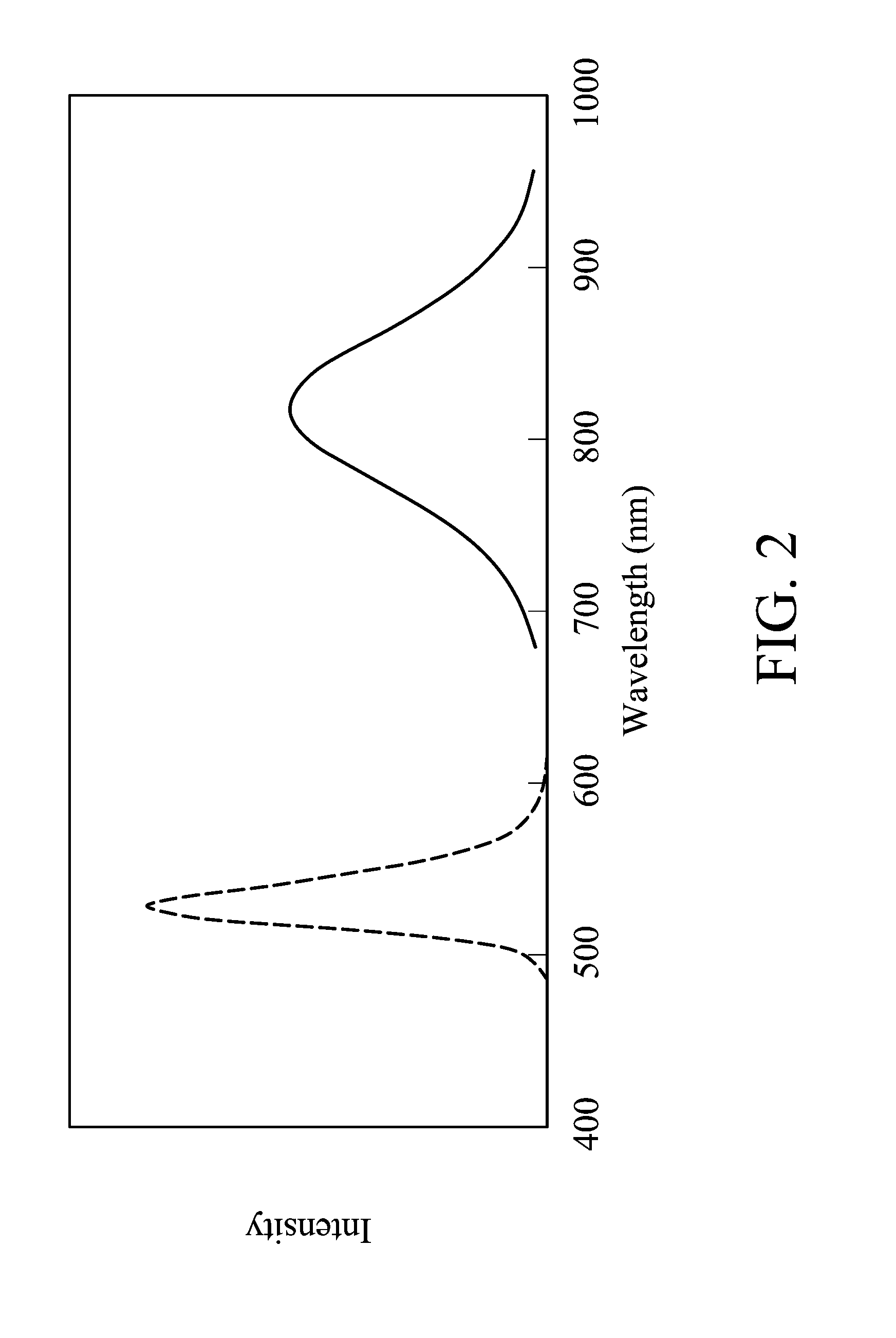
[0015]Exemplary embodiments of a light emitting device can effectively emit infrared light with high intensity by utilizing a light emitting chip and phosphor powder.

Problems solved by technology

The conventional infrared LEDs, however, have weak intensities and narrow light emitting wavelength ranges.

Method used


Image

  • Light emitting device and electronic device using the same
  • Light emitting device and electronic device using the same
  • Light emitting device and electronic device using the same

Examples


Embodiment Construction

[0023]The following description is of a mode for carrying out the invention. This description is made for the purpose of illustrating the general principles of the invention and should not be taken in a limiting sense. The scope of the invention is best determined by reference to the appended claims. Wherever possible, the same reference numbers are used in the drawings and the descriptions to refer the same or like parts.

[0024]The present invention will be described with respect to embodiments and with reference to certain drawings, but the invention is not limited thereto and is only limited by the claims herein. The drawings described are only schematic and are non-limiting. In the drawings, the size of some of the elements may be exaggerated and not drawn to scale for illustrative purposes. The dimensions and the relative dimensions do not correspond to actual dimensions to practice the invention.

[0025]The present invention will be described with respect to embodiments of a meth...


PUM


Abstract

A light emitting device and an electronic device using the same are provided. The light emitting device includes a light emitting chip having a wavelength between 460 nm and 650 nm and phosphor powders, in which the phosphor powders can be stimulated by light emitted from the chip to emit light with a wavelength between 700 nm and 1200 nm. The phosphor powders are selected from the group consisting of Cu-doped CdS, Cu-doped SeS, Cu-doped CdTe and combinations thereof.

Description

CROSS REFERENCE TO RELATED APPLICATIONS[0001]This Application claims priority of Taiwan Patent Application No. 098112990, filed on Apr. 20, 2009, the entirety of which is incorporated by reference herein.BACKGROUND OF THE INVENTION[0002]1. Field of the Invention[0003]The present invention relates to a light emitting device, and in particular, to a high intensity infrared light emitting device.[0004]2. Description of the Related Art[0005]Light emitting diodes (LEDs) have been widely applied in various fields. For example, visible LEDs comprising blue light, red light and green light LEDs can be applied in the illumination and display fields. And infrared LEDs, illuminating light in an invisible light region can be applied in the wireless remote control and sensing fields.[0006]Generally, the method for fabricating the conventional infrared LEDs comprises using GaAs as a substrate, and depositing a light emitting layer with materials similar to the substrate, for example, GaAs or GaAl...

Claims


Application Information

Patent Timeline
IPC IPC(8): H01L33/00
CPCC09K11/584C09K11/881C09K11/883H01L33/502H05B33/14H01L2224/48091H01L2924/00014
Inventor LIU, YU-HUAN
Owner EVERLIGHT ELECTRONICS
Learn More