Starter for starting internal combustion engine

a technology of starting engine and starting wire, which is applied in the direction of motor/generator/converter stopper, dynamo-electric converter control, instruments, etc., can solve the problems of wires being broken, wires being broken, and the electrical connection of electromagnetic actuators and controllers being susceptible to wire breakage, so as to reduce the risk of wire breakage

Inactive Publication Date: 2010-10-21
DENSO CORP
View PDF14 Cites 42 Cited by
  • Summary
  • Abstract
  • Description
  • Claims
  • Application Information

AI Technical Summary

Benefits of technology

[0026]Thus, even if the starter is installed in an engine room of a motor vehicle, the starter reduces the risk of the wires that ...

Problems solved by technology

Normal starters for cranking the engine essentially require configurations that withstand frequent vibration because they are directly subject to the frequent vibration due to the engine rotation.
As a result, the frequent vibration due to the engine rotation may cause the ...

Method used


Image

  • Starter for starting internal combustion engine
  • Starter for starting internal combustion engine
  • Starter for starting internal combustion engine

Examples


first embodiment

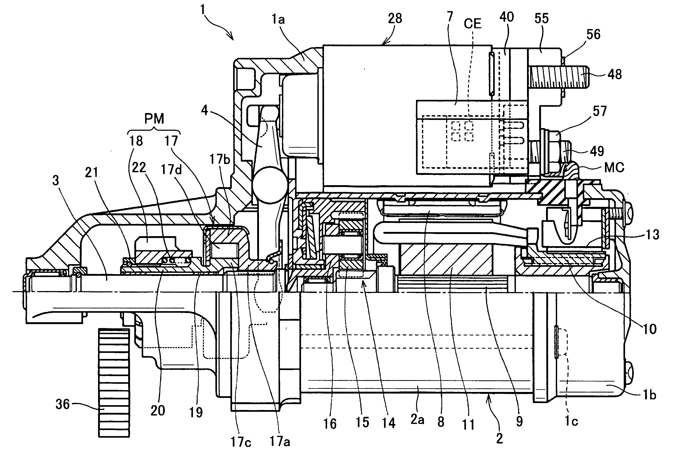
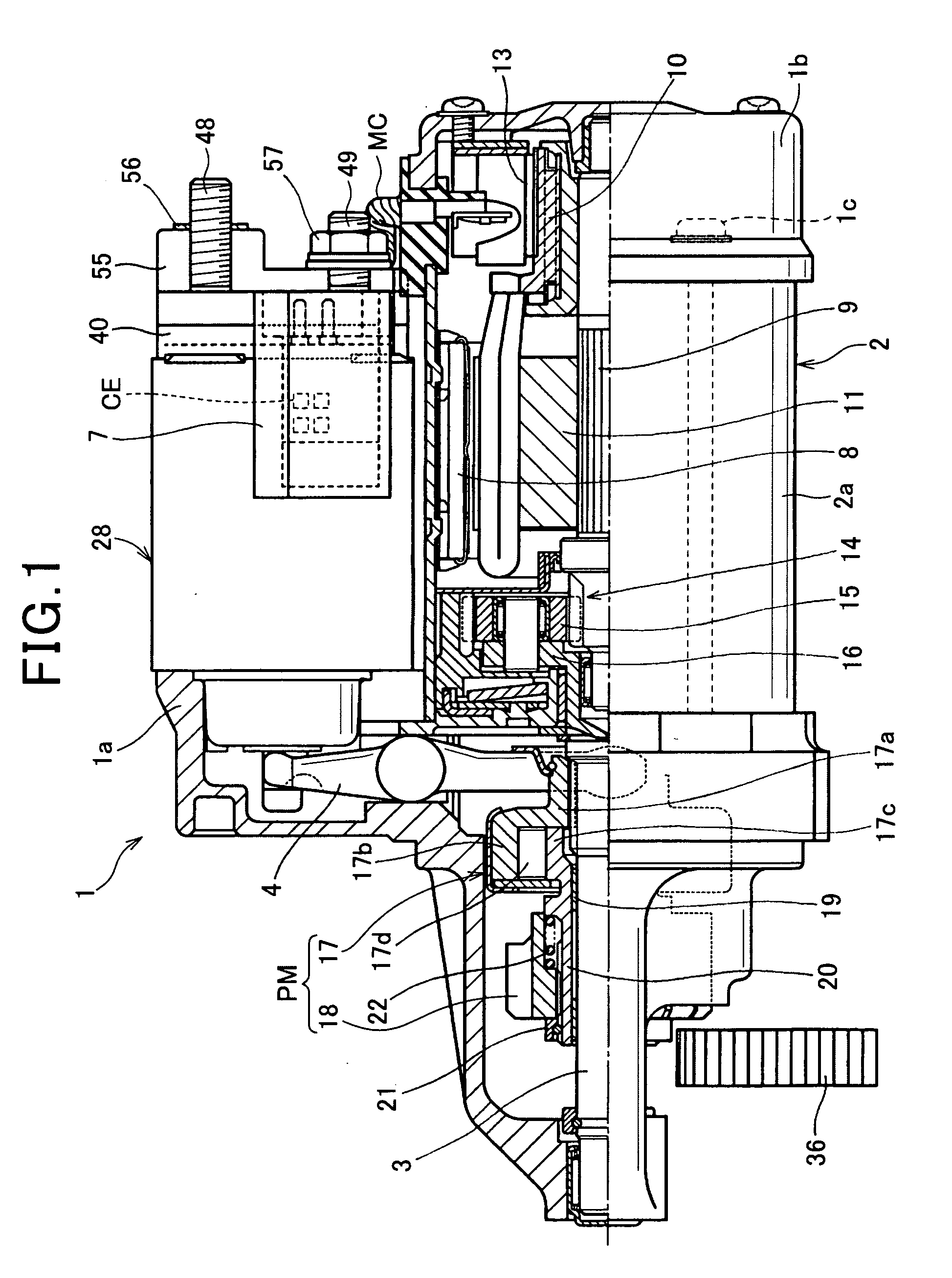
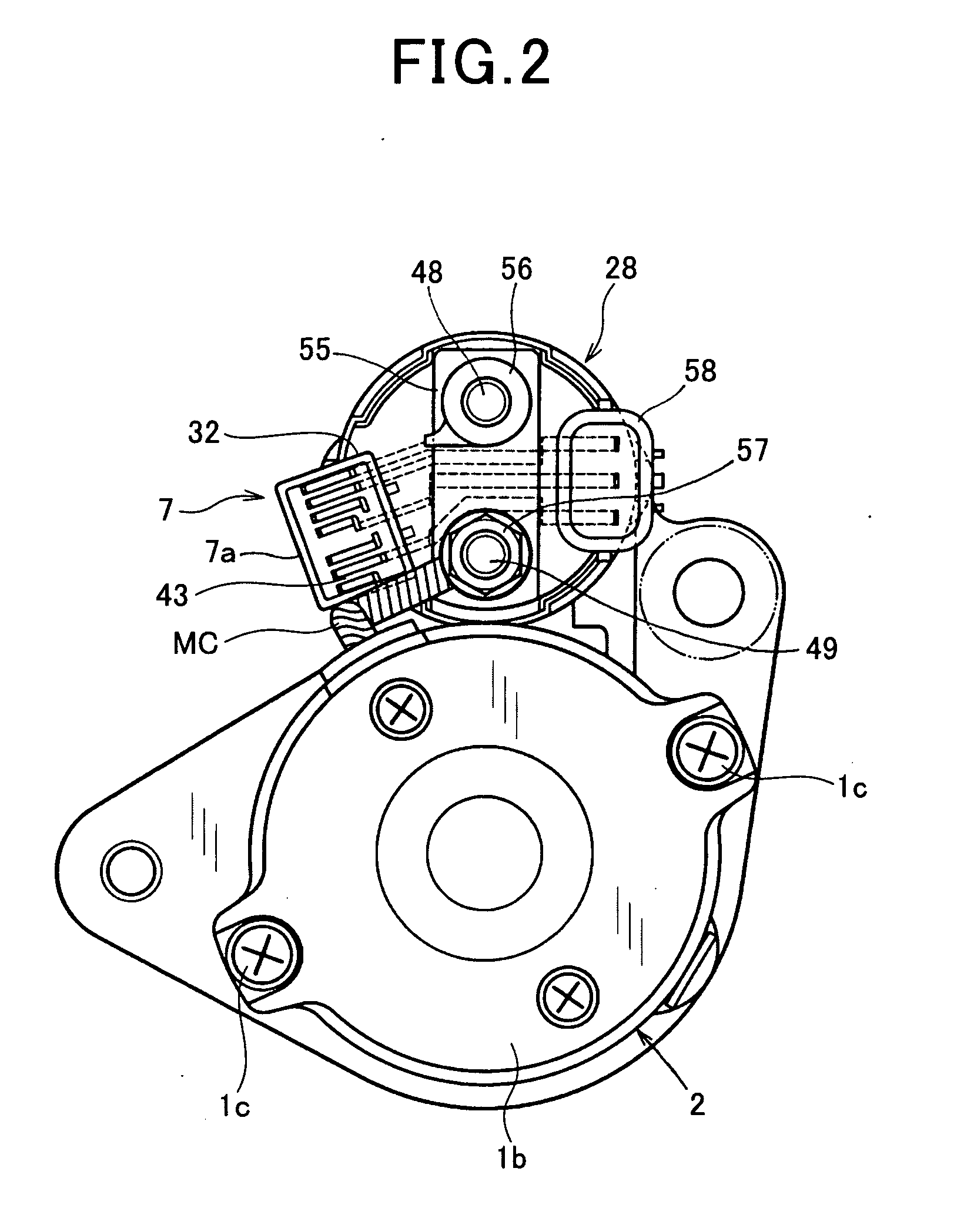
[0058]Referring to FIGS. 1 to 4, a starter 1 according to the first embodiment of the present invention is installed in a motor vehicle. The motor vehicle is equipped with an idle reduction system for automatically controlling the stop and restart of an internal combustion engine (referred to simply as “engine”) installed in the motor vehicle. The starter, idle reduction system, and the engine are placed in an engine room of the motor vehicle.

[0059]Specifically, the starter 1 includes a front housing (front frame) 1a, an end housing (end frame) 1b, a motor 2, an output shaft 3, an electromagnetic (solenoid) actuator 5 having a shift lever 4, an electromagnetic (solenoid) switch 6, and an idle-reduction ECU (Electronic Control Unit) 7 as an example of controllers according to the present invention.

[0060]The motor 2 includes an outer annular yoke 2a fastened from both axial ends by the front and end housings 1a and 1b with through bolts 1c. The front and end housings 1a and 1b and the...

second embodiment

[0158]Referring to FIGS. 5A and 5B, a starter 1A according to the second embodiment of the present invention is configured such that the modular idle-reduction ECU 7 is fixedly mounted on the end housing 1b of the motor 2.

[0159]As an example of the mounting arrangement of the idle-reduction ECU 7 according to the second embodiment, a mount 60 is attached to the end housing 1b of the motor 2 by, for example, welding, and the resin case 7a of the idle-reduction ECU 7 is fixedly mounted on the mount 60 by, for example, fastening the resin case 7a to the mount 60 with screws. Note that, in the second embodiment, as the wiring members, wires 33 and 44 are used in place of the metal plates 33 and 44.

[0160]This configuration of the starter 1A allows the length of each of the wires 33 and 44 for electrical connection between the solenoid device 28 and the idle-reduction ECU 7 to be reduced in comparison to the structure of the WO Patent Publication set forth above in which: the switch is di...

third embodiment

[0163]Referring to FIGS. 6A and 6B, a starter 1B is configured such that the modular idle-reduction ECU 7 is fixedly mounted on the outer annular yoke 2a of the motor 2.

[0164]As an example of the mounting arrangement of the idle-reduction ECU 7 according to the third embodiment, a mount 62 is attached to one end of the outer annular yoke 2a of the motor 2 by, for example, welding; this one end is close to the end housing 1b. The resin case 7a of the idle-reduction ECU 7 is fixedly mounted on the mount 62 by, for example, fastening the resin case 7a to the mount 62 with screws. Note that, in the third embodiment, as the wiring members, wires 33 and 44 are used in place of the metal plates 33 and 44.

[0165]This configuration of the starter 1B allows the length of each of the wires 33 and 44 for electrical connection between the solenoid device 28 and the idle-reduction ECU 7 to be reduced in comparison to the structure of the WO Patent Publication set forth above in which: the switch i...


PUM


Abstract

In a starter for starting an internal combustion engine with a first output shaft to which a ring gear is coupled, a motor has a second output shaft to which a movable pinion member is coupled and is operative to, when energized, rotate the second output shaft. A solenoid device includes a solenoid actuator linked to the movable pinion member. The solenoid actuator is configured to, when activated, shift the movable pinion member toward the ring gear to be engaged with the ring gear. The solenoid device includes a solenoid switch configure to, when activated, energize the motor. The solenoid actuator and the solenoid switch are integrated with each other to provide the solenoid device. A controller module is configured to individually control an activation of the solenoid actuator and an activation of the solenoid switch. The controller module is mounted on the solenoid device.

Description

CROSS REFERENCE TO RELATED APPLICATIONS[0001]This application is based on Japanese Patent Applications 2009-101090, 2009-121758, 2009-195735, 2009-212966, and 2009-282783 filed on Apr. 17, 2009, May 20, 2009, Aug. 26, 2009, Sep. 15, 2009, and Dec. 14, 2009. This application claims the benefit of priority from the Japanese Patent Applications, so that the descriptions of which are all incorporated herein by reference.FIELD OF THE INVENTION[0002]The present invention relates to starters including: an electromagnetic actuator for shifting a pinion to an internal combustion engine, and an electromagnetic switch for energizing and deenergizing the motor. More particularly, the present invention relates to such starters designed to individually control the operation of the electromagnetic actuator and that of the electromagnetic switch.BACKGROUND OF THE INVENTION[0003]Some types of vehicles installed with an engine automatic stop-and-restart system, such as an idle reduction control syste...

Claims


Application Information

Patent Timeline
IPC IPC(8): F02N11/08H02K5/22H02K11/00H02P1/10
CPCF02D2400/18F02D2400/21F02D2400/22F02N11/087F02N11/0855F02N15/067Y02T10/48F02N11/0844F02N15/006Y02T10/40
Inventor USAMI, SHINJIYOSHIDA, YASUYUKIMURATA, MITSUHIRONIIMI, MASAMINOTANI, HIDEYAOKUMOTO, KAZUSHIGEKATO, AKIRASAITO, MIKIO
Owner DENSO CORP
Why Eureka
Try Eureka