
System for maintaining security of evidence throughout chain of custody

Active Publication Date: 2010-10-21
VERDASEE SOLUTIONS
View PDF6 Cites 100 Cited by
  • Summary
  • Abstract
  • Description
  • Claims
  • Application Information

AI Technical Summary

Benefits of technology

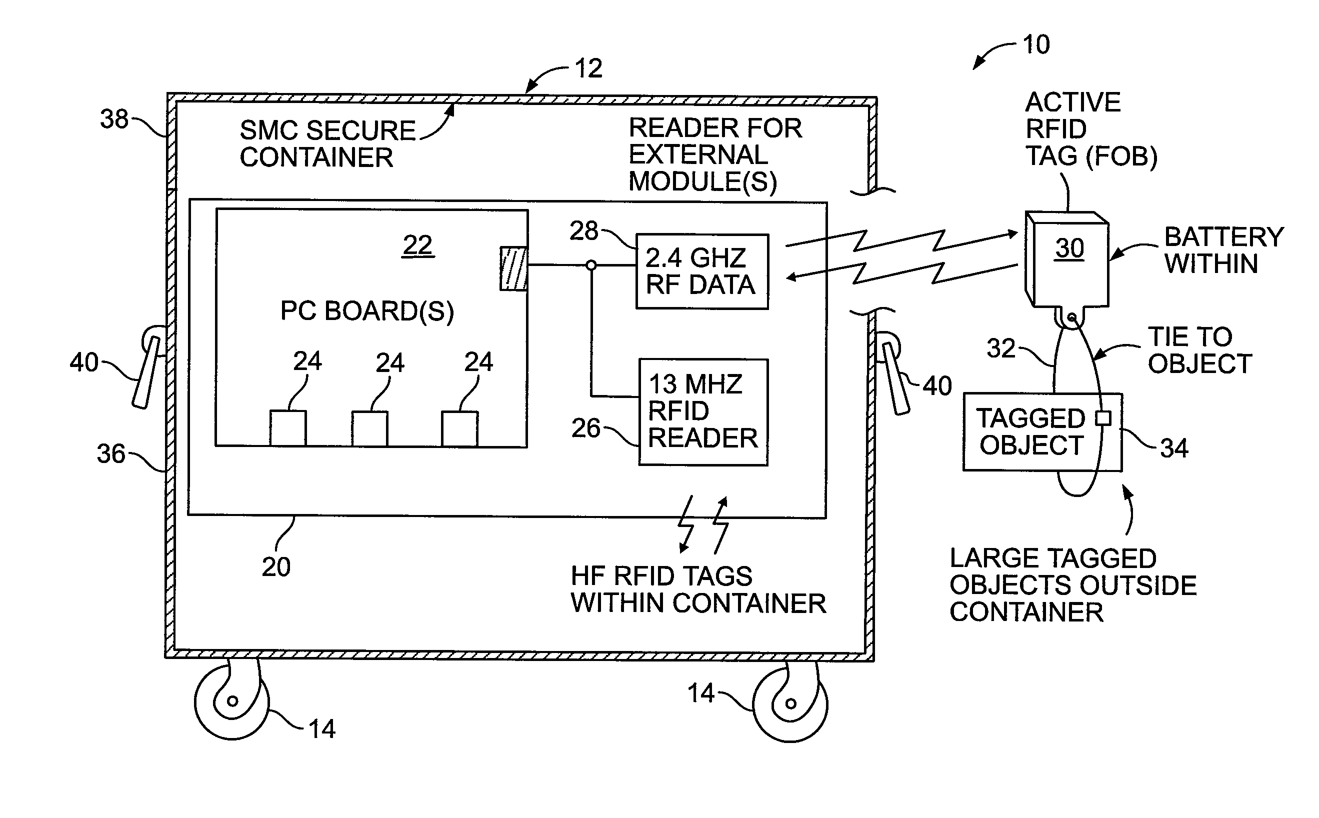
[0010]More specifically, the present invention is directed to a system and method for maintenance, verification and certification of the chain of evidence of forensic items is maintained. The system and method includes the use of trackable and auditable SMCs along with a comprehensive, configurable, computer-enabled record keeping system. The evidence items are loaded into, or RF tagged for electronic association with, one or more SMC container(s) having an embedded electronic security system providing RF position location and tracking, RF contents inventory, self-monitoring and / or pollable condition sensors and auditable electronic locks, to provide a secure, verifiable chain of custody of and access to forensic evidence from crime scene to courtroom, and through all intervening stages of access by authorized personnel, including law enforcement, evidence techs, experts, defense counsel, prosecutors, trial and appellate judges and jury.
[0044]The load / unload RF tag serial number data also can be loaded into the memory of the electronic lock key (or and the lock itself), so that upon relocking of the SMC by the electronic key, the key has the comparative record of load vs unload inventory. In an extension of this load / unload audit, the receiving location (evidence storage facility, lab, courthouse, prosecutors office, defense counsel) may have RF sensor / readers at selected location(s) on site so that the physical location of the tagged evidence is tracked while on site. Thus, the lab is fitted with a reader, and as the received evidence items are brought out for analysis, that on site reader adds the item to the local in-process inventory. In addition, the lab's reader can relay the log-in data via short range RF, e.g., 2-6 GHz transmission, to the RF transceiver of the SMC, and the SMC in turn can act as a relay to the evidence storage facility or prosecutors office, or suitable tracking authority (law enforcement agency, or the like) via its RF cell network VPN communications system. As withdrawals are made from the SMC by the lab, the RF tag information may be read and relayed as described. Thus, the SMC system provides a secure and comprehensive evidence tracking with provision for full handling and audit trail records.

Problems solved by technology

Conversely, there are cases where accused persons may have been unjustly prosecuted or convicted by tainted evidence.
Often there is a substantial time delay between crime and trial.
Much of the logging records are not kept electronically, can be altered or lost, and the evidence is subject to damage or deterioration during storage.
In some instances, evidence is lost along the way, including even during presence at the trial court.
Evidence disappears, or its integrity is compromised or questioned.
The cost of maintaining the evidence is substantial, and the many steps and multiple accessing of the evidence has the possibility of mistakes more a possibility than a probability.
Proving integrity of evidence is also an element of the prosecutor's case that adds substantially to the cost of trial and often involves significant time of court, counsel and jury.
In addition, some evidence items, including money, valuable items and drugs are targets for theft.
Responsibility is often excused or deflected by reference to sloppy or negligent procedures, lack of funding for secure storage facilities.
The result is a substantial burden on the criminal justice system, as well as creates a significant embarrassment when loss / mishandling of evidence events occur.

Method used


Image

  • System for maintaining security of evidence throughout chain of custody
  • System for maintaining security of evidence throughout chain of custody
  • System for maintaining security of evidence throughout chain of custody

Examples


first embodiment

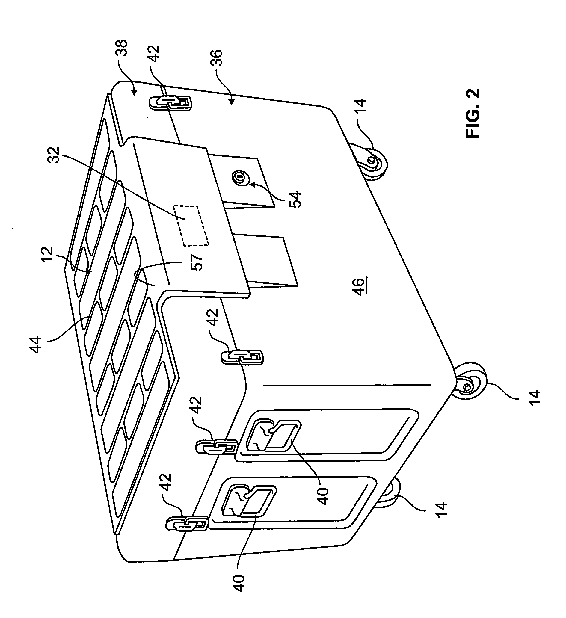
[0067]The SMCs, both embodiments, include hinged, L-shaped, flanged lock plate 56 that covers the opening side of the SMC lid 38. The lock plate covers a housing for an electronic lock 54. When raised, the lock plate completely covers the lock body and its connection to the electronics package inside the SMC. In a first embodiment, the lock plate includes a latch plate with a hole that engages the plunger of the electronic lock. In addition, the lock plate, when closed, covers a pair of spaced, cam or snap type lid locks 42. The lid locks enable the lid to be cinched down, hermetically sealing the lid to the box. The lid locks are also completely covered by the flanged lock cover plate. Thus, to resist tampering; there are no exposed parts that act as a purchase for a pry bar.

second embodiment

[0068]In a second embodiment, a smaller, Courier size container having only 2 wheels and a telescoping handle in a configuration akin to a large roll-away suitcase, shown in FIG. 3A-3D, may be used for smaller collections of evidence items. It also includes the electronics package and functionalities described herein. In this configuration, the L-shaped lock plate is hinged adjacent the side wall edge of the lid, see FIG. 3C, so that it folds down. The lock mechanism is contained in the lock plate, and a striker plate having a hole there-through to receive and engage the male lock shackle mechanism is secured to the side wall of the container. The striker plate includes the lock contacts to complete the electrical circuit to the lock electronics contained in the electronics package inside the courier container.

[0069]In both container embodiments, the preferred lock system is a hardened electronic lock mechanism that permits identification of which “keyholder” (approved access-person...


PUM


Abstract

An evidence chain of custody system that is application-specific auditable and trackable secure smart mobile containers (SMC) for securely storing evidence items that are collected at crime scenes and search locations pursuant to subpoenas or warrants. Each SMC includes a electronics package that can read RF tags applied to evidence bags or totes placed in the SMC or for oversized items, associated with the event or scene, that are tagged with active RF tags. The electronics package also includes condition sensors and an RF transmitter module to permit remote reporting and monitoring of GPS / RSSI location and condition. The SMC includes an electronic lock that provides access security and an audit trail of all opening, closing, and other events.

Description

CROSS REFERENCE TO RELATED APPLICATION[0001]This application is a Non-Provisional Application of U.S. Provisional Patent Application 60 / 871,027, filed on Dec. 20, 2006 entitled System for Maintaining Security of Evidence Throughout Chain of Custody. This application is also a Continuation-In-Part Application which claims priority to U.S. application Ser. No. 11 / 959,444, filed on Dec. 18, 2007 entitled Underdeck Carrier System for Mobile Containers for Segregating Product Types in Common Shipment, to U.S. application Ser. No. 11 / 375,304, filed on Mar. 13, 2006 entitled Private Pallet-Box Cargo Shipping System, and to U.S. application Ser. No. 11 / 128,879, filed on May 13, 2005 entitled Small Pallet-Box Cargo Container, and to U.S. application Ser. No. 10 / 330,149, filed on Dec. 27, 2002 entitled Private Pallet-Box Cargo Shipping system, which issued as U.S. Pat. No. 7,011,214 on Mar. 14, 2006, which claims priority from U.S. Provisional Application No. 60 / 374,871, filed on Apr. 22, 200...

Claims


Application Information

Patent Timeline
IPC IPC(8): G08B13/14
CPCB60P3/03B60P3/14G01S19/48G01S19/35G01S5/0205
Inventor BRACKMANN, ROGERS F.KOSSNAR, DENNIS
Owner VERDASEE SOLUTIONS
Learn More