
Projection Device

a projection device and projection technology, applied in the direction of projectors, color television details, instruments, etc., can solve the problems of difficult to use an existing mobile phone for the purpose of viewing pictures or showing materials for presentation, and achieve the effect of prolonging the projection tim

Inactive Publication Date: 2010-10-21
KYOCERA CORP
View PDF5 Cites 27 Cited by
  • Summary
  • Abstract
  • Description
  • Claims
  • Application Information

AI Technical Summary

Benefits of technology

[0018]According to the present invention as stated above, it is possible to lengthen a projecting time at a battery-powered operation.
[0019]Advantage or significance of the present invention will be further understood from the description of an embodiment below. However, the following embodiment is merely an example for carrying out the present invention, and the present invention is not limited by the following embodiment.

Problems solved by technology

It is therefore hard to use an existing mobile phone for the purpose of viewing pictures or showing materials for presentation.

Method used


Image

  • Projection Device
  • Projection Device
  • Projection Device

Examples


Embodiment Construction

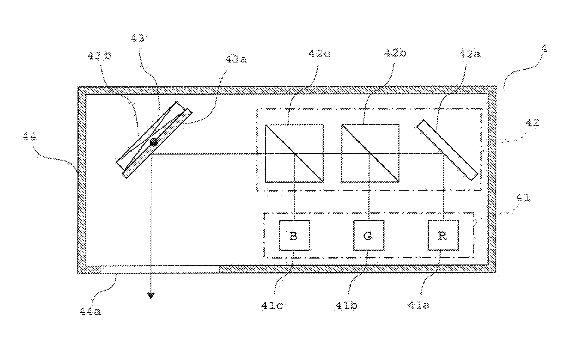
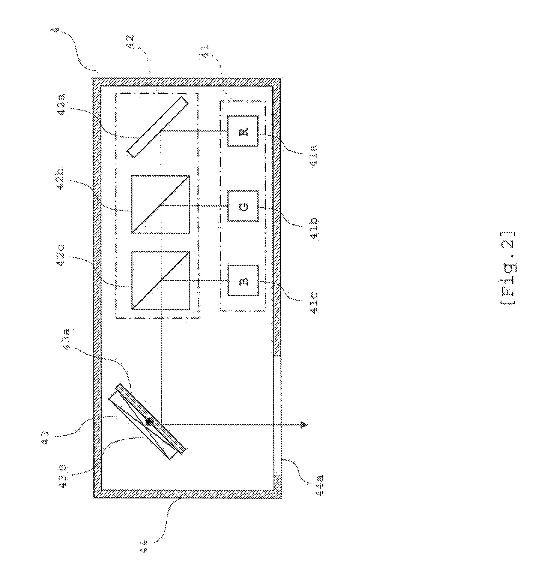
[0034]An embodiment of the present invention will be described below with reference to the attached drawings. In this embodiment, a projection device of the present invention is applied to a mobile phone.

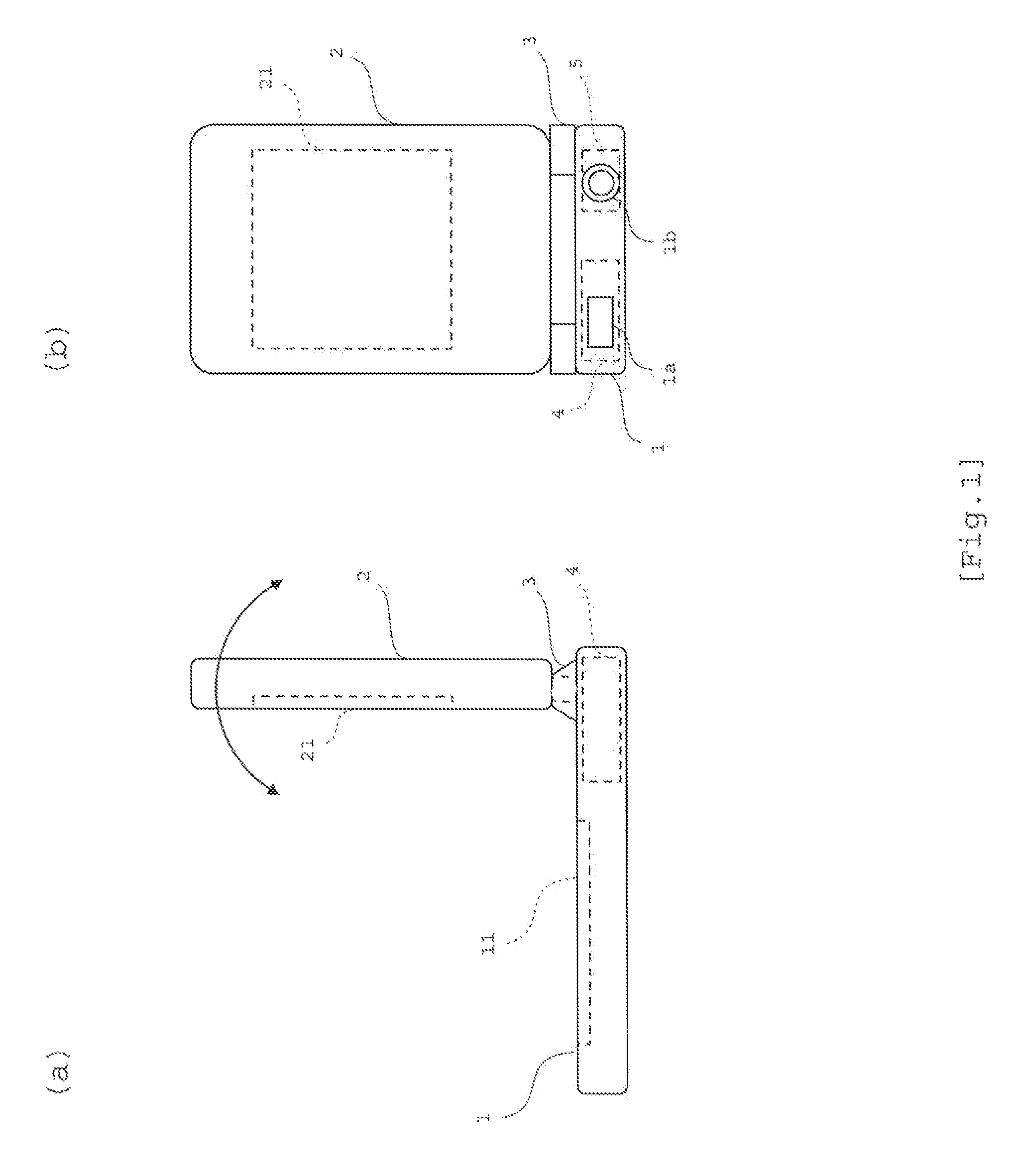
[0035]FIG. 1 is a diagram showing an external configuration of the mobile phone: FIG. 1 (a) is a side view of the mobile phone with a display part 2 made upright in an almost vertical position with respect to an operation part 1; and FIG. 1 (b) is a rear view of the mobile phone in the same state.

[0036]The mobile phone includes the operation part 1 and the display part 2. The operation part 1 has a keypad 11 disposed on a front side thereof. The keypad 11 includes various keys such as a key for switching among various modes (camera shooting mode, e-mail send / receive mode, Internet mode, and projector mode), a call start key, a call end key, number / character input keys, and others. The display part 2 has a liquid crystal display 21 on a front side thereof. The display part 2 is rotat...


PUM


Abstract

[Object]To provide a scan-type projection device that can lengthen a projecting time during a battery-powered operation.[Constitution] If a battery 600 is sufficiently charged, an actuator control part 120 drives a movable mirror 43 so as to form a normal turning angle, and an image signal processing part 130 drives a light source part 41 so as to irradiate laser lights with predetermined gradations to one pixel region for a normal irradiation time t1. Accordingly, an image with a normal screen size is displayed on a projection plane. Meanwhile, if the battery becomes low in remaining level, the actuator control part 120 drive the movable mirror 43 so as to form a small turning angle, and the image signal processing part 130 drives the light source part 41 so as to irradiate laser lights with predetermined gradations to one pixel region for a short irradiation time t2. Accordingly, an image with a reduced screen size is displayed on a projection plane.

Description

TECHNICAL FIELD[0001]The present invention relates to a projection device, and is suitable particularly for use in a scanning-type projection device that projects an image by scanning a projection plane with light.BACKGROUND ART[0002]As a general projection device (hereinafter referred to as “projector”), there is a known scanning-type projector that has three laser lights of red, green, and blue as a light source, and scans a projection plane with these laser lights using a movable mirror composed of micro electro mechanical systems (MEMS) and the like to thereby projects a color image (Patent Document 1). Such a projector can be reduced in size and lowered in power consumption, and therefore incorporating the projector into small-sized devices such as mobile phones has been considered in recent years.[0003]For example, a mobile phone has a display part (liquid crystal display) that is made significantly small in dimensions due to its size limit as compared with a personal computer...

Claims


Application Information

Patent Timeline
Patent Type & Authority Applications(United States)
IPC IPC(8): G03B21/14
CPCG02B26/105G03B9/02H04N9/3173H04N9/3129G03B21/14G03B21/208G02B27/18
Inventor YAMASHITA, REIKONISHIMURA, YOSHIHIRO
Owner KYOCERA CORP
Learn More