Optical sedimentation recorder

a sedimentation recorder and optical technology, applied in the field of optical sedimentation recorders, can solve the problems of affecting the calcification of phytoplankton and zooplankton, the biological and physical processes that sequester carbon remain poorly understood, and the upper kilometers of the ocean are both biologically quite activ

Active Publication Date: 2010-10-21
RGT UNIV OF CALIFORNIA
View PDF7 Cites 10 Cited by
  • Summary
  • Abstract
  • Description
  • Claims
  • Application Information

AI Technical Summary

Benefits of technology

[0019]The sampling module can be deployed in several modes. In one mode it can be affixed to a cable moored to a buoy and simply allowed to sink to a fixed depth, the depth limited by the length of the attached cable. In the carbon flux recorder mode, the sampling module is attached to a buoyancy vehicle, such as one produced by the Instrument Development Group of the Scripps Institution of Oceanography, and set adrift, to be positioned at various depths. In yet another embodiment, in either mode, multiple sampling modules can be deployed together. Using such a multiple deployment affords several advantages, one of them being that readings of the multiple units can be compared, as a means of calibrating one against the other. In addition, due to the long duty cycle of these sedimentation recorders, and the expense of positioning them, the one unit can serve as a backup to the other unit in case of battery, or other type of component failure.

Problems solved by technology

Acidification of seawater due to human generated CO2 is believed to negatively impact both calcifying phytoplankton and zooplankton.
Despite the important role that the oceans play in the global carbon cycle and of the regulation of levels of atmospheric CO2, the biological and physical processes that sequester carbon remain poorly understood.
This is due in large part because of the difficulties of making continuous observations in the vast waters of the world's oceans, including those areas of extreme weather, ice, winds and the like.
Yet, the upper kilometers of the ocean are both biologically quite active, and very observation-poor.
Conventional ship based sampling methods such as the collecting of particles by filtration using rosette-mounted bottles or large volume in situ filtration cannot adequately capture the spatial and temporal variability of biomass material in the ocean.
Further, such ship based tender is time consuming, and expensive, and this thus severely limits the number of sampling stations which can be established.

Method used


Image

  • Optical sedimentation recorder
  • Optical sedimentation recorder
  • Optical sedimentation recorder

Examples


Embodiment Construction

[0031]The various features and advantages of the present invention will become more fully apparent from the following description taken in conjunction with aforementioned drawings.

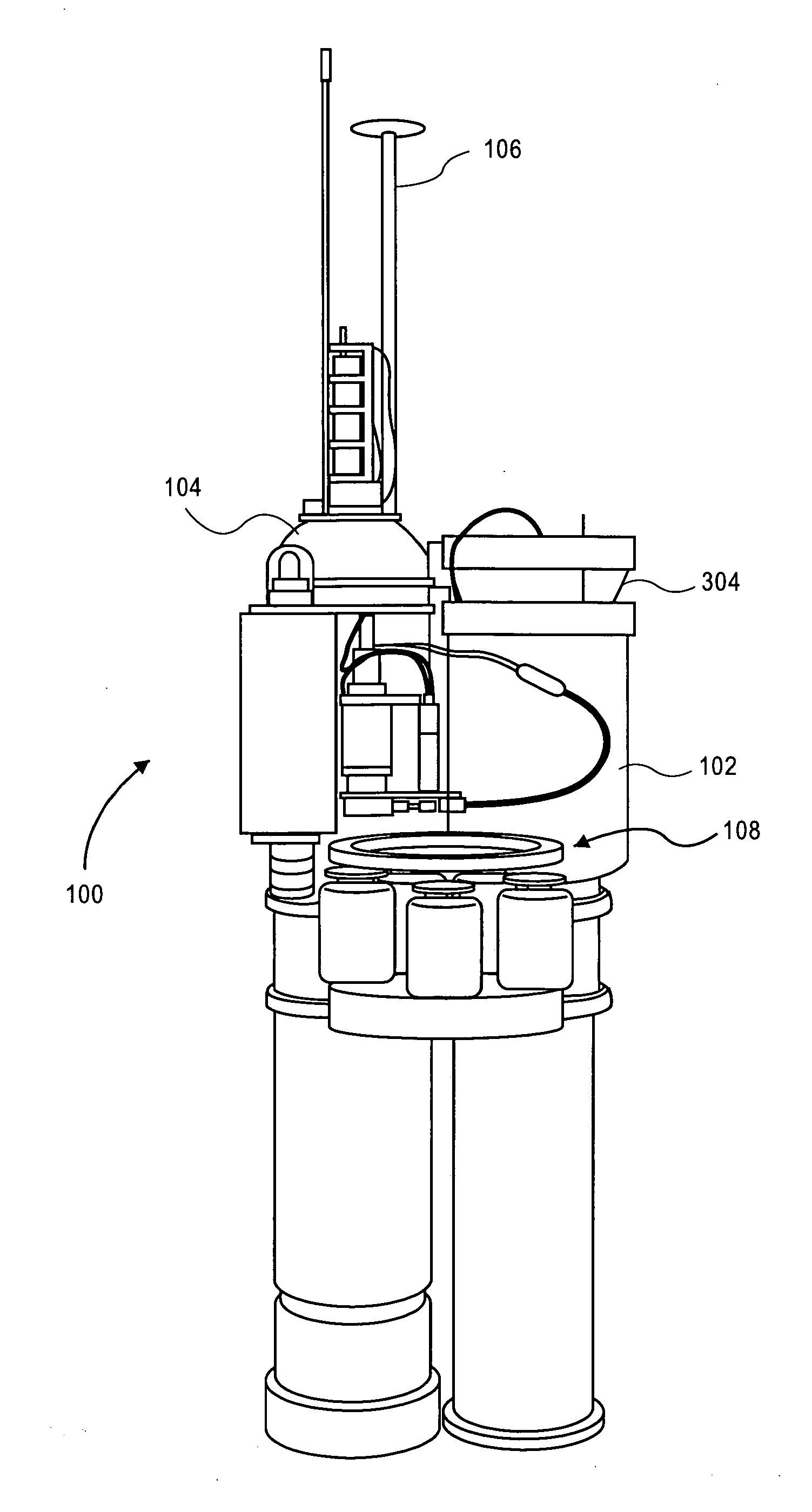
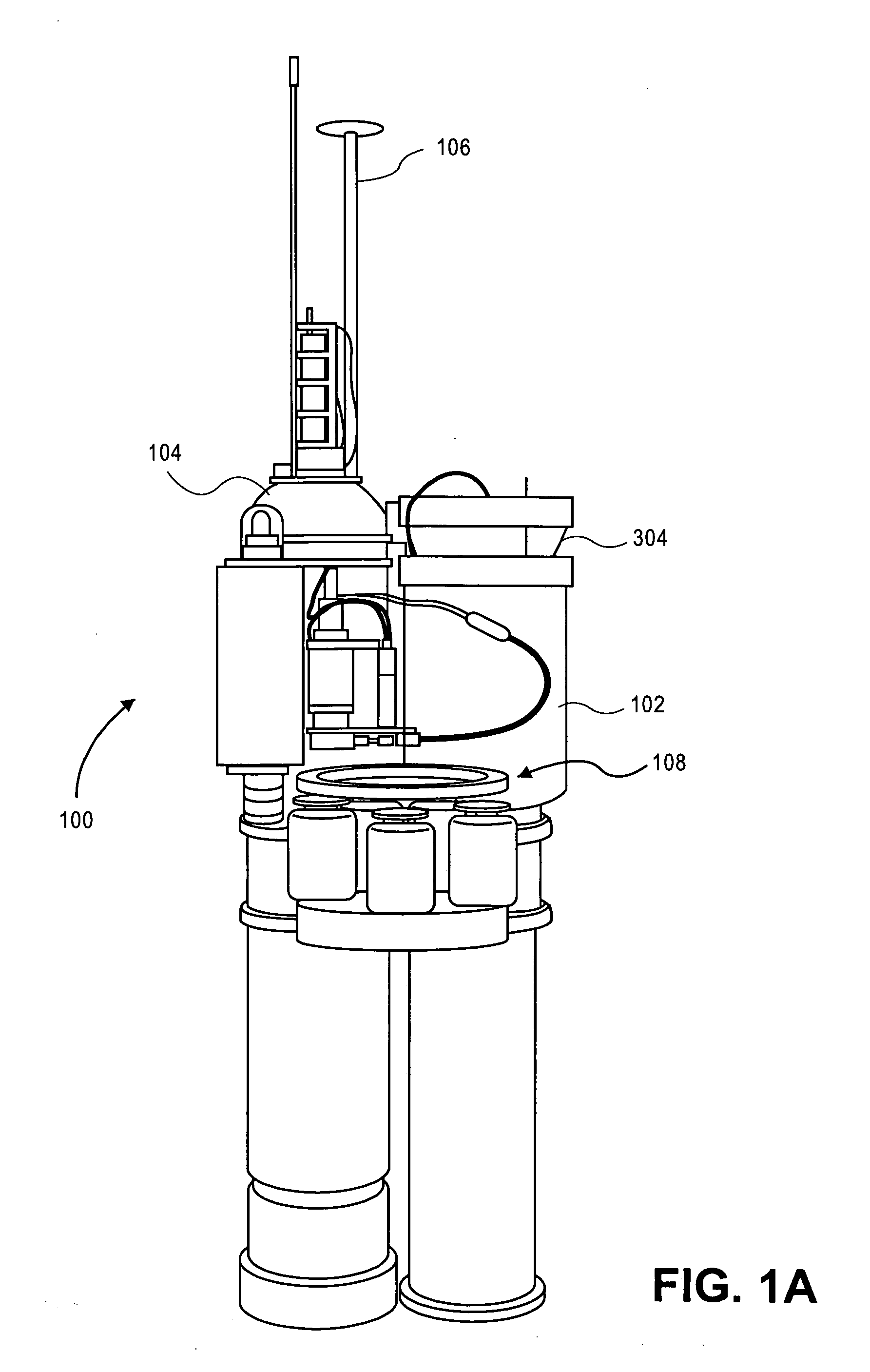
[0032]With reference now to FIG. 1A, the carbon flux explorer unit of the invention 100 is illustrated, with sampling platform 102 joined to buoyancy engine 104, a profiling float. Batteries (not shown) in both units are used to power the various mechanical devices (such as pumps, etc) illuminator lamps, and electronic components. A transmission cable (also not shown) allows for cross communication of data and computer commands between platform 102 and buoyancy engine 104. A satellite communications unit incorporated into module 104 is designed to uplink to overhead satellites through satellite antenna 106 when the carbon flux explorer is at the ocean's surface.

[0033]Unit 100 is designed to free float once placed in the ocean, and follows the currents in a lagrangian fashion. Because of this relatively ran...


PUM


Abstract

A robotic optical sedimentation recorder is described for the recordation of carbon flux in the oceans wherein both POC and PIC particles are captured at the open end of a submersible sampling platform, the captured particles allowed to drift down onto a collection plate where they can be imaged over time. The particles are imaged using three separate light sources, activated in sequence, one source being a back light, a second source being a side light to provide dark field illumination, and a third source comprising a cross polarized light source to illuminate birefringent particles. The recorder in one embodiment is attached to a buoyancy unit which is capable upon command for bringing the sedimentation recorder to a programmed depth below the ocean surface during recordation mode, and on command returning the unit to the ocean surface for transmission of recorded data and receipt of new instructions. The combined unit is provided with its own power source and is designed to operate autonomously in the ocean for extended periods of time.

Description

CROSS REFERENCE TO RELATED APPLICATIONS[0001]This application claims the priority benefit to PCT Application PCT / US2008 / 012607, filed Nov. 7, 2008, entitled Optical Sedimentation Recorder, which in turn claimed the benefit of priority to U.S. Provisional Application 60 / 988,240 filed Nov. 15, 2007, the contents of both of said applications hereby incorporated herein by reference as if fully set forth in their entirety.STATEMENT OF GOVERNMENTAL SUPPORT[0002]The invention described and claimed herein was made in part utilizing funds supplied by the U.S. Department of Energy under Contract No. DE-AC03-76SF00098, and more recently under DE-AC02-05CH11231. The government has certain rights in this invention.BACKGROUND OF THE INVENTION[0003]1. Field of the Invention[0004]This invention relates generally to a method of indirectly measuring the concentrations of carbon dioxide in the oceans, and more specifically to a robotic device which can operate autonomously in the oceans for extended p...

Claims


Application Information

Patent Timeline
Patent Type & Authority Applications(United States)
IPC IPC(8): G06K9/00G01J4/04H04N7/18
CPCG01N1/12G01N21/23G01N2015/045G01N21/59G01N21/49
Inventor BISHOP, JAMES K.B.
Owner RGT UNIV OF CALIFORNIA
Why Eureka
Try Eureka