Image forming method

a technology of image forming and forming direction, which is applied in the direction of instruments, electrographic process equipment, developers, etc., can solve the problems of difficult control in such a direction, difficult control to view a specific color at a specific angle, etc., and achieve the effect of improving the uniformity of the fixing direction

Inactive Publication Date: 2010-10-21
KONICA MINOLTA BUSINESS TECH INC
View PDF2 Cites 30 Cited by
  • Summary
  • Abstract
  • Description
  • Claims
  • Application Information

AI Technical Summary

Benefits of technology

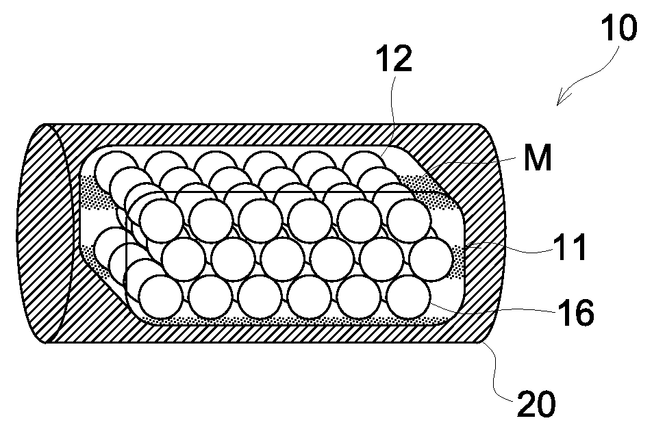
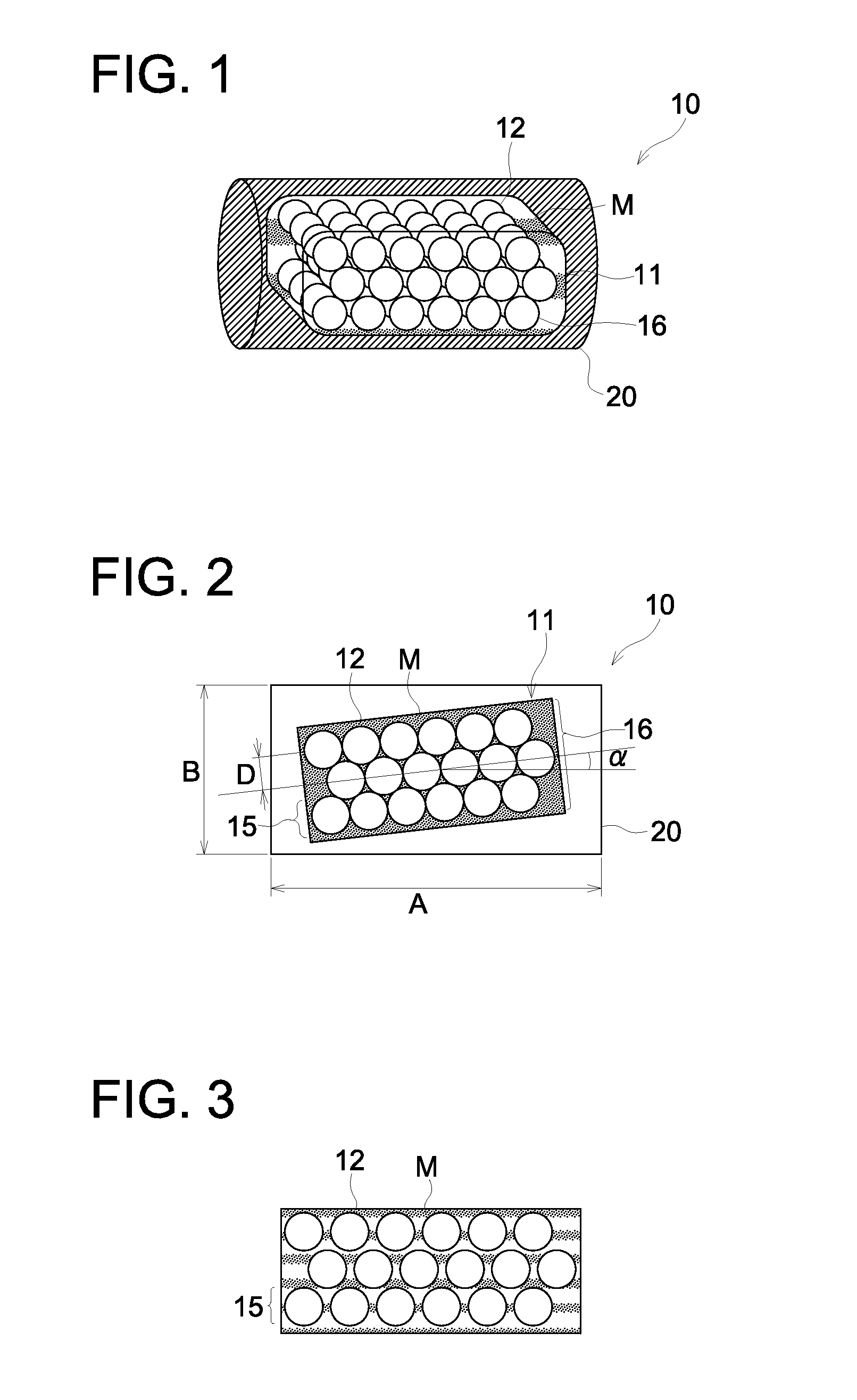
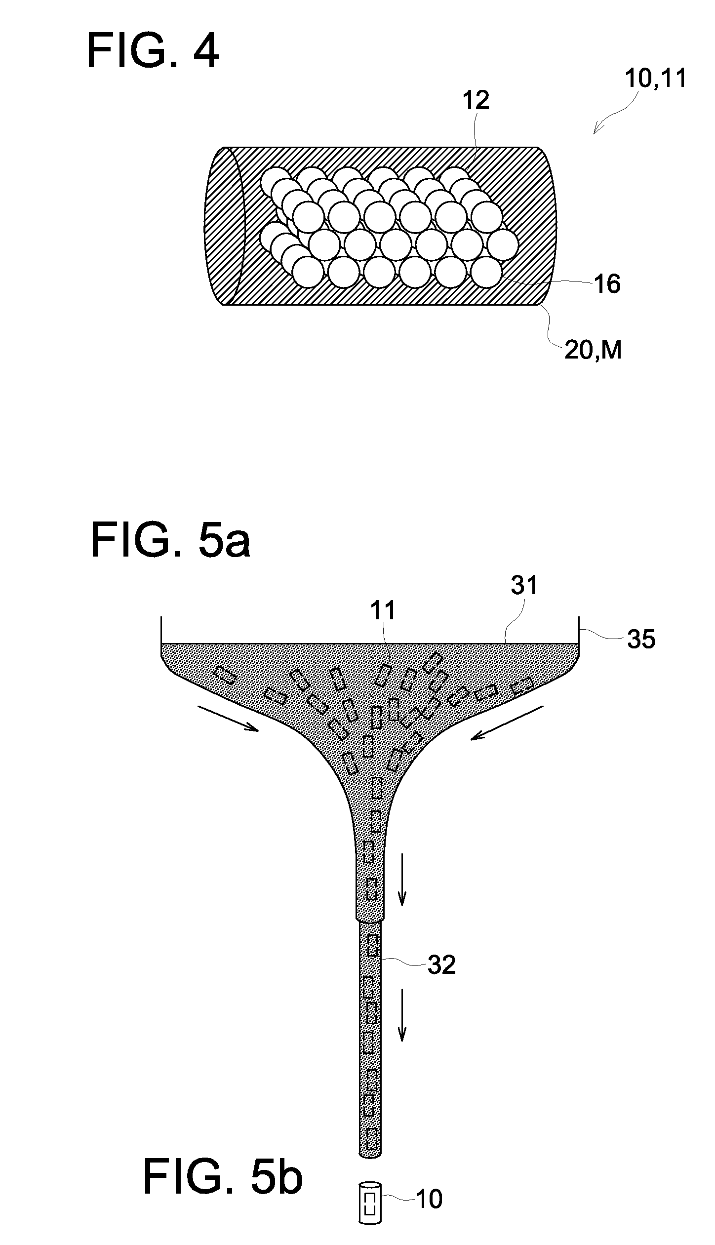
[0012]In the image forming method of the invention, a color particle which contains a color-exhibitive piece exhibiting a structural color inclined at a specific angle and exhibits anisotropy, is used, whereby enhanced uniformity of the fixing direction of the color-exhibitive piece is achieved in the obtained image, wherein different colors are visible depending on the viewing angle, and there can be formed an image in which a specific color is visible at a specific angle.

Problems solved by technology

In such as an interference pigment, different colors are visible depending on the viewing angle and to allow a specific color to be visible at a specific angle, it is necessary to make the fixing direction of the individual interference pigment uniform; however, control in such a direction has been difficult in the prior art.
Accordingly, there were produced problems such that a color visible at a specific angle became varied, rendering it difficult to have control to view a specific color at a specific angle.

Method used


Image

  • Image forming method
  • Image forming method
  • Image forming method

Examples


synthesis example 1

of Microparticles for Structural Color

[0122]A mixture of 72 parts by mass of styrene, 20 parts by mass of n-butyl acrylate and 8 parts by mass of acrylic acid was heated to 80° C. to prepared a monomer mixture solution. Further, 0.2 part by mass of sodium dodecylsulfonate was dissolved in 163 parts by mass of deionized water at 80° C. to obtain a surfactant solution. The monomer mixture solution and the surfactant solution were mixed and stirred for 30 min. by a mechanical dispersing machine, CLEARMIX (produced by M TECHNIQUE Co., Ltd.) to prepare an emulsified dispersion. To a reaction vessel equipped with a stirring device, a heating and cooling device, a nitrogen introducing device and a charger for raw material or an auxiliary agent were added to the foregoing emulsified dispersion and an aqueous surfactant solution of 0.1 g of sodium dodecylsulfonate dissolved in 142 parts by mass and the internal temperature was raised to 80° C. with stirring at 200 rpm under a stream of nitro...


PUM

PropertyMeasurementUnit
angleaaaaaaaaaa
diameteraaaaaaaaaa
diameteraaaaaaaaaa

Abstract

A color particle is disclosed, comprising a color-exhibitive piece which comprises microparticles for structural color and a matrix and is dispersed in a binder resin, wherein the color particle meets the following requirement:1.5≦A / B≦5.0wherein A is a major axis diameter of the color particle and B is a minor axis diameter of the color particle; and an angle of a longitudinal direction of the color-exhibitive piece to a major axis direction of the color particle falls within a range of ±20 degrees.

Description

[0001]This application claims priority from Japanese Patent Application No. 2009-098763, filed on Apr. 15, 2009, which is incorporated hereinto by reference.FIELD OF THE INVENTION[0002]The present invention relates to an image forming method by using colored particles exhibiting a structural color.BACKGROUND OF THE INVENTION[0003]There has been a desire for preparation of notes for invitation to a home party, a small-scaled store flyer or advertisements by a full-color printer. Also there has been desired special colors rich in decorativeness, such as a special color in which different colors are visible depending on the viewing angle, for example in an opal. To represent such a structural color, there was proposed an image forming material containing an interference pigment such as, for example, pearl mica, as described in, for example, Japanese Patent Application Publication JP 2002-351144A and 2004-061822A.[0004]In such as an interference pigment, different colors are visible dep...

Claims


Application Information

Patent Timeline
Patent Type & Authority Applications(United States)
IPC IPC(8): G03G9/087G03G13/06
CPCG03G9/081G03G9/08711G03G2215/0602G03G15/08G03G9/0926
Inventor SHIRAI, AYANAGASE, TATSUYANISHIMURA, MOTOI
Owner KONICA MINOLTA BUSINESS TECH INC
Why Eureka
Try Eureka