
Tension band

a technology of tension band and stent, which is applied in the field of tension band apparatus, can solve the problems of inability to achieve in-place tensioning, lack of ease and reliability in the securement of the assembly to the vertebral body, etc., and achieve the effect of limiting separation and reducing the likelihood of subsiden

Inactive Publication Date: 2010-10-21
WARSAW ORTHOPEDIC INC
View PDF46 Cites 18 Cited by
  • Summary
  • Abstract
  • Description
  • Claims
  • Application Information

AI Technical Summary

Benefits of technology

The present invention provides a device for linking vertebral bodies with an implant therebetween. The device includes a flexible member that can be placed in tension and a connector apparatus for securing the flexible member to the vertebral bodies. The flexible member can be modified to increase its usefulness and can be treated to promote bony integration and inhibit subsidence or dislodgement of the implant. The device can be used to link vertebral bodies with an implant and can help prevent separation of the vertebral bodies and inhibit the growth of soft tissue adhesion to the flexible member. The device can be easily visualized and can help the surgeon assess the degree of tension in the flexible member and the orientation and location of the band. The flexible member can be modified to have indicia for visual and radiographic assessment of the tension and can be treated with a therapeutic substance to elute it over time. The connector apparatus can include end caps, mechanical fasteners, or other securement methods. The device can help prevent dislodgement of the implant and can provide bony integration to the vertebral bodies.

Problems solved by technology

Several problems, limitations and disadvantages have commonly been associated with tension band assemblies of conventional design, including inaccuracies in achieving in-place tensioning thereof, lack of ease and reliability in the securement of the assemblies to the vertebral bodies, and the need to provide associated therapeutic and other treatment to the surgical site of the tension band installation.

Method used


Image

  • Tension band
  • Tension band
  • Tension band

Examples


Embodiment Construction

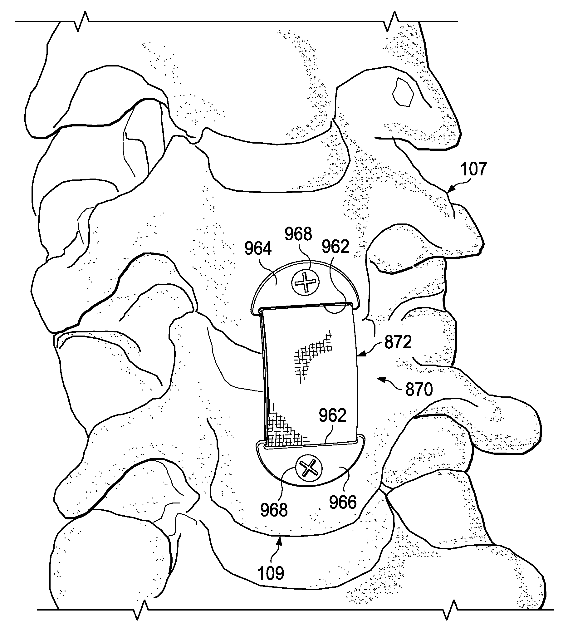
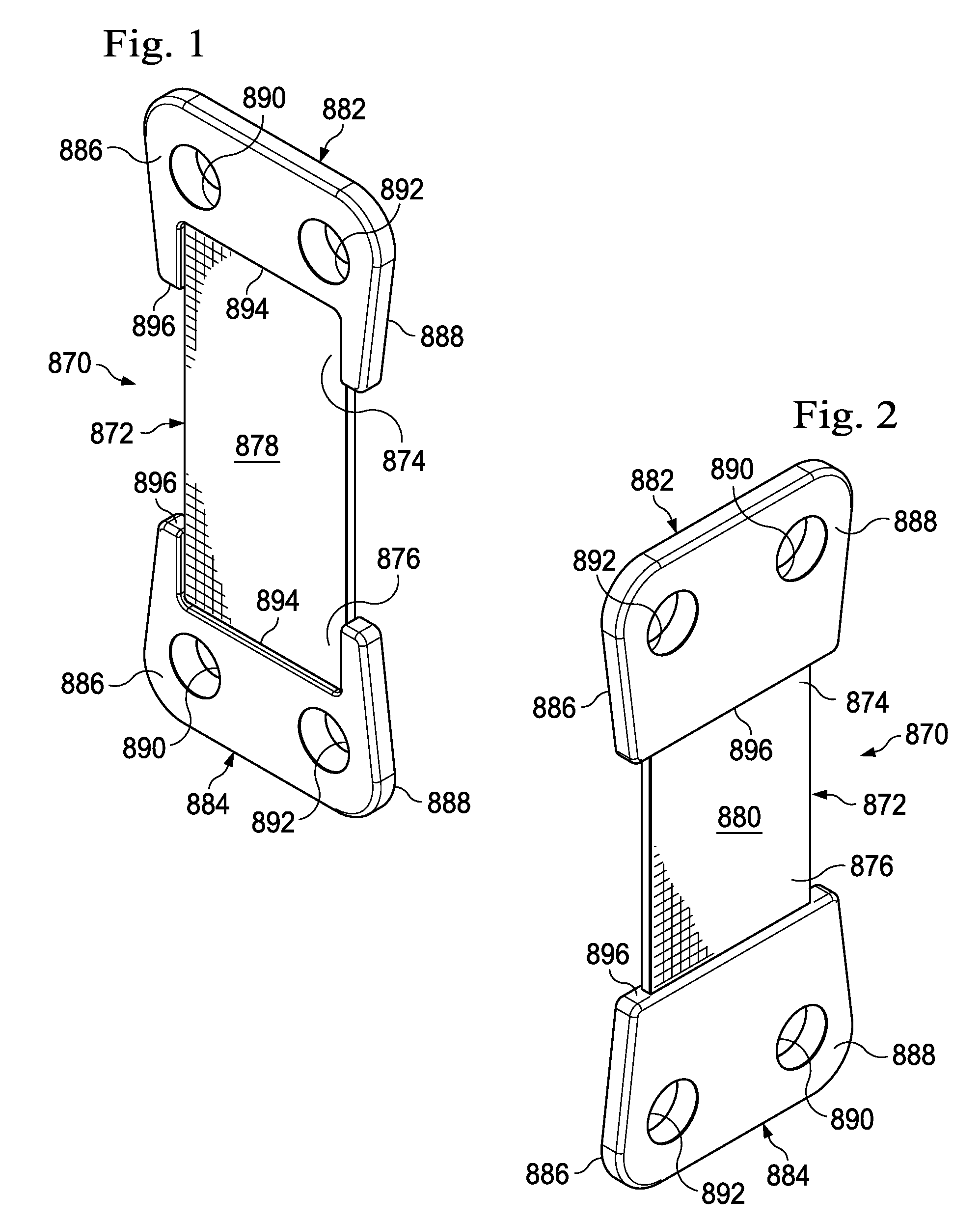
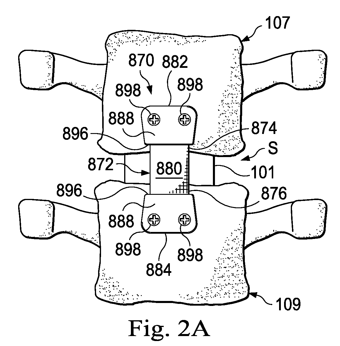
[0033]Turning first to FIGS. 1 and 2, perspectively illustrated therein is a vertebral linking apparatus in the form of an assembly 870 which may be utilized, as subsequently described herein, to link two vertebral bodies (such as the upper and lower vertebrae 107,109 in FIG. 2A) in a manner that may, for example (1) assist in holding the apparatus in a preferred location and / or orientation and / or affect, inhibit, contribute to or limit separation of the vertebral bodies, and (2) cover, inhibit or reduce the likelihood of subsidence of or enhance the potential blocking or hinder the dislodgment of a spinal implant (such as the illustrative implant 101 schematically depicted in FIG. 2A) from between the vertebral bodies. Implant 101 may have a variety of different configurations and structures to suit the particular surgical procedure. For example, implant 101 may be a spacer such as a cage for stabilization or an artificial disc for preserving motion.

[0034]Vertebral linking assembly...


PUM


Abstract

Various embodiments of a vertebral tension band assembly and associated connection structure are provided. The tension band assemblies may be attached to vertebral bodies to, for example, connect one vertebrae to another, retain the band in approximately a preferred position by application of tension to the band during insertion and / or limit, impede, inhibit, reduce or interfere with the separation from one vertebra to another and may further block, impede, interfere with, inhibit, reduce or present an obstacle to dislodgement of a spinal implant from between the vertebrae to which it is attached. Flexible band portions of the assemblies may be treated and / or configured to promote bony integration between the band and the associated vertebrae, limit tissue adhesion to the band, and / or to elute a therapeutic substance from the installed band to the surgical site.

Description

BACKGROUND OF THE INVENTION[0001]The present invention generally relates, for example, to apparatus used to correctively link two or more vertebral bodies, and more particularly relates to tension band apparatus connectable to vertebral bodies.[0002]Various flexible tension band assemblies have been previously proposed for attachment to vertebral bodies to limit the separation therebetween, and to outwardly block dislodgement of an implant disposed between the vertebral bodies. Several problems, limitations and disadvantages have commonly been associated with tension band assemblies of conventional design, including inaccuracies in achieving in-place tensioning thereof, lack of ease and reliability in the securement of the assemblies to the vertebral bodies, and the need to provide associated therapeutic and other treatment to the surgical site of the tension band installation. A need exists for alleviating these problems, limitations and advantages. It is to this need and others th...

Claims


Application Information

Patent Timeline
Patent Type & Authority Applications(United States)
IPC IPC(8): A61B17/70A61B17/84
CPCA61B17/7059
Inventor FOLEY, KEVIN T.HAID, REGIS W.METCALF, JR., NEWTON H.COATES, BRADLEY J.SHARP, DAVID ALANDIAZ, CHRIS MICHAELRICHARDSON, VIRGINIA LEIGHJUSTIS, JEFF R.TRIEU, HAI H.NYCZ, JEFFREY H.MARIK, GREG C.DREWRY, TROY D.THIELE, RICHARD J.LINDEMANN, GARY S.
Owner WARSAW ORTHOPEDIC INC
Learn More