Spray Angle Measurement Apparatus and Method

a measurement apparatus and angle technology, applied in the direction of instruments, structural/machine measurement, television systems, etc., can solve the problems of not accurately assessing the performance of the orifice, the measurement does not capture actual material, and the system does not assess whether the measured emission direction matches the expected emission direction within an acceptable tolerance range , to achieve the effect of improving the performance and safety of emitted materials

Inactive Publication Date: 2010-10-28
PROVERIS SCI CORP
View PDF7 Cites 5 Cited by
  • Summary
  • Abstract
  • Description
  • Claims
  • Application Information

AI Technical Summary

Benefits of technology

[0004]Embodiments of the present invention improve performance and safety of emitted materials from orifices defined by structures (e.g., nozzles) by measuring actual material emission direct...

Problems solved by technology

While existing methods and systems for emission measurements assist with characterization of emitted material (e.g., the spray) from orifices defined by structures (e.g. nozzles), the measurements do not capture actual material emission directio...

Method used


Image

  • Spray Angle Measurement Apparatus and Method
  • Spray Angle Measurement Apparatus and Method
  • Spray Angle Measurement Apparatus and Method

Examples


Embodiment Construction

[0043]A description of example embodiments of the invention follows.

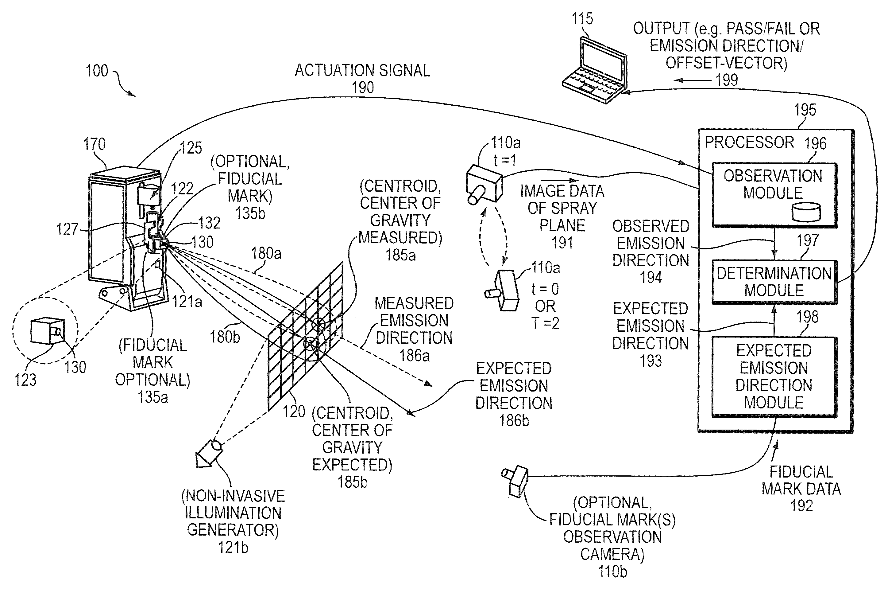
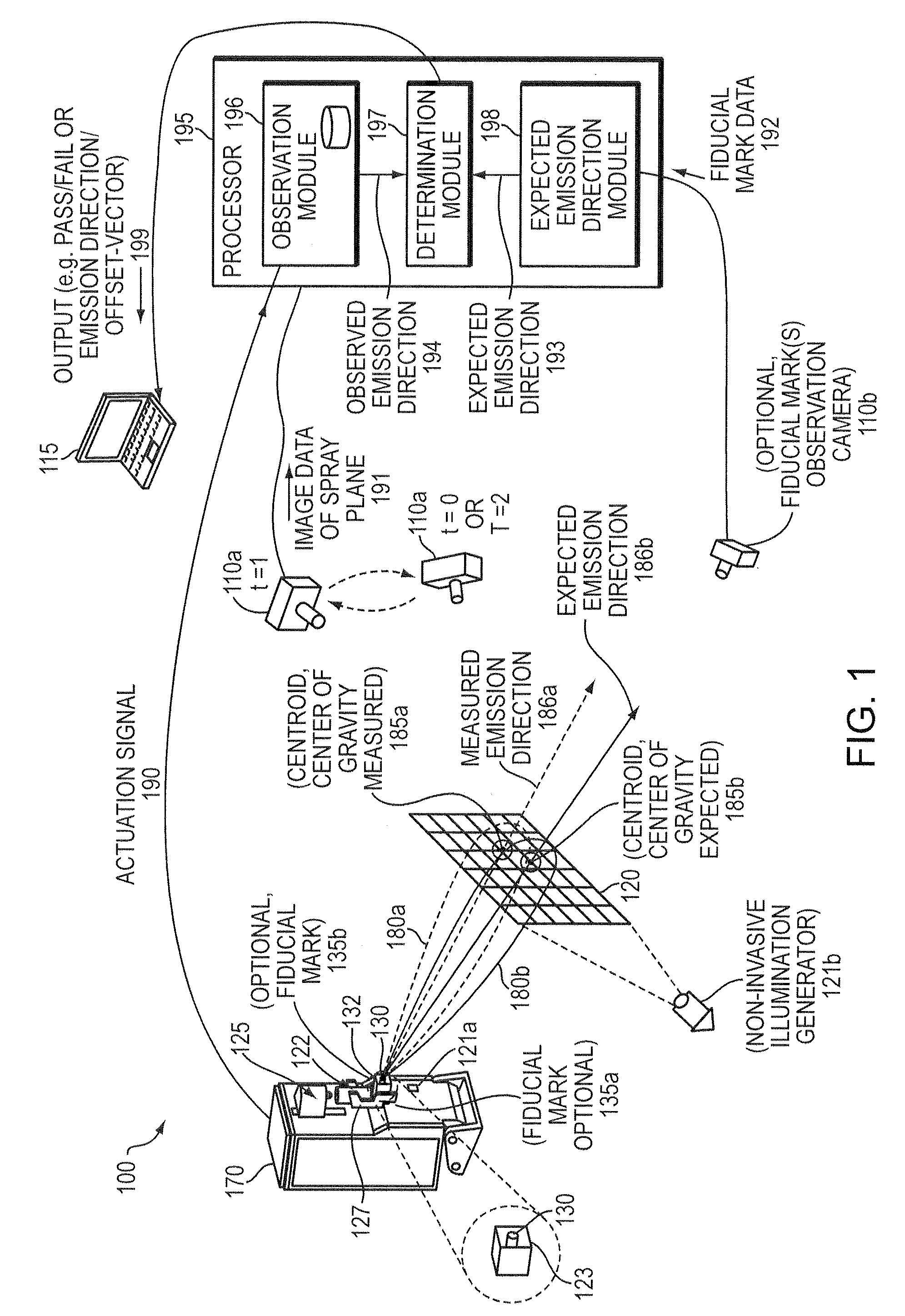
[0044]Correct operation of spray devices is critical to effective and efficient use of the material emitted from the spray devices. Manufacturing defects in the molding or machining process, improper assembly of an orifice defined by a structure, nozzle, or pump components, improper operation of the orifice's actuation system, or a combination of these or other causes may result in improper emission direction of the material emitted from the orifice of the spray device. An embodiment of the present invention serves to inspect the operation of spray devices and, in particular, determine an emission direction of the material emitted from the spray device.

[0045]Existing systems address certain root causes for improper emission direction. For example, improper operation of the orifice's actuation system may be addressed through automated actuation. Automated actuation of manually operated spray devices, such as nasal sp...


PUM


Abstract

Direction of material emitted from orifices is directly related to the effectiveness of spray devices to deliver the material to an intended location area. Improper emission direction results in material, such as medication, paint, or fuel, not reaching its intended target and causes cascading effects, such as improper patient dosing, compromised patient relief, waste, poor target coverage, missed target penetration, poor engine performance, and other safety/performance problems. An apparatus for inspecting operation of an orifice according to an example embodiment measures actual material emission direction relative to an expected material emission direction determined as a function of position and orientation of an orifice. The apparatus may confirm whether the emission direction is within an expected emission direction and accepted tolerance range. Through use of the apparatus, accurate screening of production products can be performed efficiently and manufacturing defects can be diagnosed and eliminated.

Description

RELATED APPLICATION(S)[0001]This application claims the benefit of U.S. Provisional Application No. 61 / 210,287, filed on Mar. 17, 2009, the entire teachings of which are incorporated herein by reference.BACKGROUND OF THE INVENTION[0002]A position and orientation of an orifice is a contributing factor to the effectiveness of delivering material to be emitted via the orifice to where it is intended (i.e., the target location). For example, an improper emission direction due to improper position and orientation of the orifice results in the material not reaching its intended target location. Failure to reach the target location causes cascading effects that diminish the performance of the emitted material, including, for example, improper dosing (in the case of an inhaled medication), waste, poor target coverage, missed target penetration, poor engine performance (in the case of a fuel injector, for example), or other safety and / or performance problems. Additionally, an improper emissi...

Claims


Application Information

Patent Timeline
IPC IPC(8): H04N7/18G01M99/00
CPCG01M99/008G01B11/26B05B12/004
Inventor FARINA, DINO J.DOMBACH, MATTHEW D.L'ECUYER, TIMOTHY R.PITLUK, ZACHARY W.
Owner PROVERIS SCI CORP
Why Eureka
Try Eureka