

Video Apparatus
a technology of video equipment and video input, which is applied in the field of video equipment, can solve the problems of high cost and complicated interface, and achieve the effects of reducing the number of function blocks, reducing the number of interfaces, and improving user experien
- Summary
- Abstract
- Description
- Claims
- Application Information
AI Technical Summary
Benefits of technology
Problems solved by technology
Method used
Image

Examples
embodiment 1
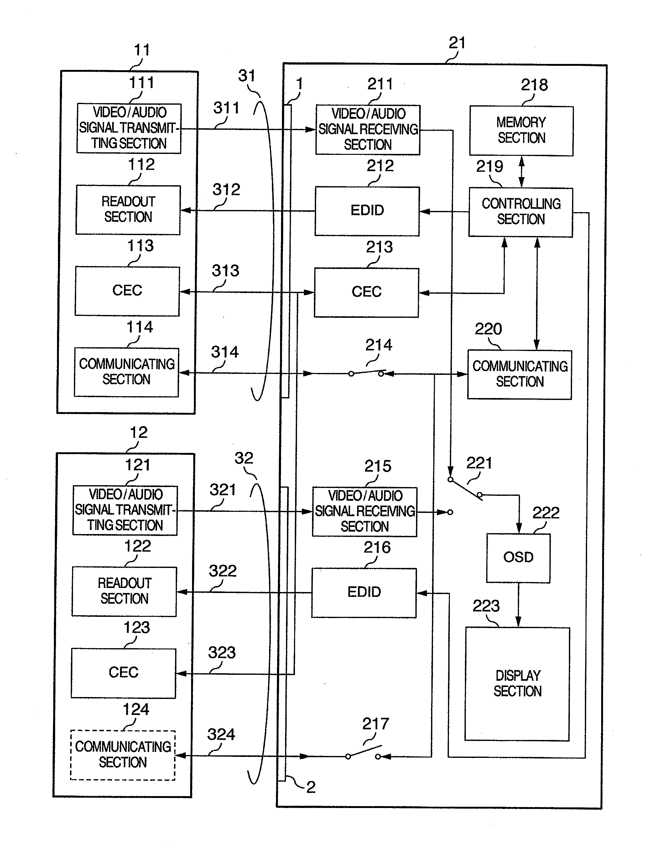
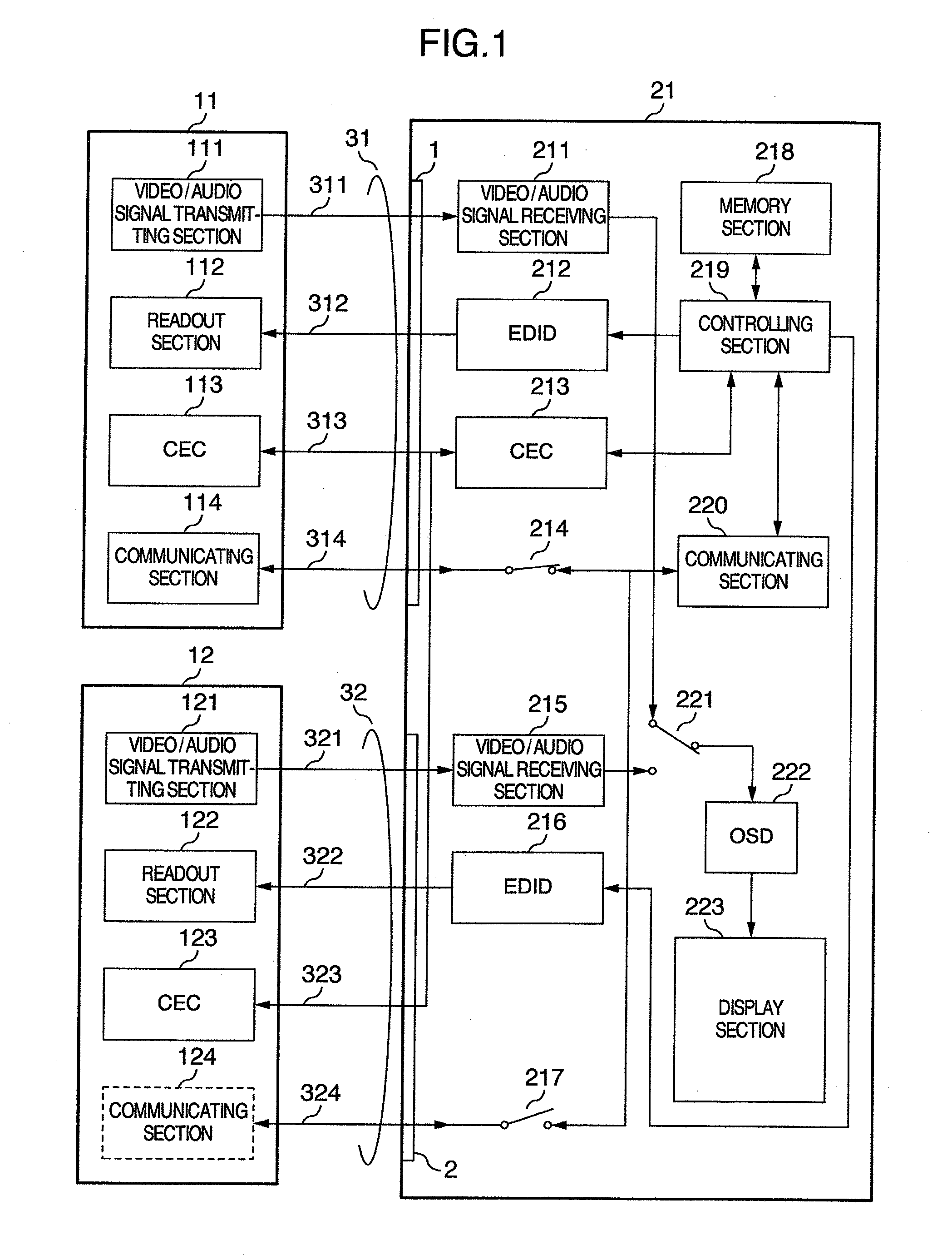
[0023]In FIG. 1 showing Embodiment 1 of the present invention, video signal sources 11 and 12 are connected with a display apparatus 21 via HDMI cables 31 and 32. The video signal sources 11 and 12 have HDMI outputs, which include video / audio signal transmitting sections 111 and 121, readout sections 112 and 122, CEC communication sections 113 and 123, and communicating sections 114 and 124, respectively. Namely, each of the video signal sources 11 and 12 has one HDMI output. The video signal sources 11 and 12 may be such as a HDD recorder, a STB or the like.
[0024]It is noted that a combination of a video signal source and a display apparatus may be termed “a video apparatus”. Further, the display apparatus 21 has a structure including a display section, but it need not be always include a display section. Instead of the display section, the display apparatus may include an output section for delivering an image signal to an external display unit.
[0025]The display apparatus 21 has H...
embodiment 2
[0040]Referring to the flow chart shown in FIG. 3, Embodiment 2 will be described in connection with transference of a signal receiving capability in which use is made of the CEC.
[0041]In the initial state 511, information such that both input sections 1 and 2 are in a standby state for the communication function is entered in the memory section 218 shown in FIG. 1, and the switches 214 and 217 are turned off.
[0042]When a communication request through the input section 1 is received under the CEC, the process moves to state 512. Information such that a communication through the input section 1 starts and a communication through the input section 2 stops is entered in the memory section 218, and the switch 214 is turned on to start the communication.
[0043]When a communication request through the input section 2 is received over the CEC, the process moves to state 513, in which a response is given over the CEC such that the communication function is unavailable at the input section 2,...
embodiment 3
[0046]Next, Embodiment 3 will be described in which it is assumed that the video signal source 11 is a combined unit having a video signal source and an audio amplifier, and in which transmission of an audio signal is taken as an example.
[0047]When the video apparatus 21 selects the video signal source 12 to receive therefrom a video / audio signal through the TDSM line 321, the video apparatus 21 is capable of displaying the video signal received from the video signal source 12. However, without an arrangement for transmitting an audio signal from the video signal source 12 to the video signal source 11 serving as an audio amplifier, a high performance reproduction of the audio signal in the audio amplifier will be impossible. This is due to the fact that the TMDS line 311 can only transmit a video / audio signal from the video signal source 11 serving as an audio amplifier to the display apparatus 21 and signal transmission in the opposite direction is impossible therewith. As a novel...
PUM
 Abstract
Description
Claims
Application Information