Method for producing magnetic recording medium and magnetic recording/reproducing apparatus

a technology of magnetic recording medium and recording/reproducing apparatus, which is applied in the field of producing magnetic recording medium and magnetic recording/reproducing apparatus, can solve the problems of reducing the bit error rate, affecting the enhancement of recording density, and affecting the quality of recording, and achieves good head-floatability, high recording density, and excellent partitionability

Inactive Publication Date: 2010-10-28
SHOWA DENKO KK
View PDF8 Cites 0 Cited by
  • Summary
  • Abstract
  • Description
  • Claims
  • Application Information

AI Technical Summary

Benefits of technology

[0045]According to the present invention drawn to a method for producing a magnetic recording medium wherein a magnetic layer is formed on a non-magnetic substrate and then a magnetic recording pattern is formed on the magnetic layer, a magnetic recording medium can be provided which is characterized in that a good head-floatability is ensured, and the magnetic recording pattern is partitioned by the regions exhibiting excellent partitionability and the signal interferes occurring between the adjacent partitioned regions in the pattern are suppressed, and that a high recording density can be achieved.
[0046]Further according to the present invention, a magnetic recording / reproducing apparatus can be provided which is equipped with the above-mentioned magnetic recording medium, and thus, exhibits good head-floatability, and the magnetic recording pattern is partitioned with excellent partitionability and the signal interferes occurring between the adjacent partitioned regions are suppressed, and thus, which apparatus has high recording density characteristics.

Problems solved by technology

However, with an increase of the track density, magnetic recording information is liable to interferring with each other between adjacent tracks, and magnetization transition regions in the boundary regions thereof as a noise source tend to impair the SNR.
These problems result in lowering in bit error rate and impede the enhancement of the recording density.
However, with a decrease in the bit size, the minimum magnetization volume per bit becomes small, and the recorded data are tend to disappear due to magnetization reversal caused by heat fluctuation.
This operation is advantageous in that the influence of the adjacent tracks can be minimized, but it is disadvantageous in that the reproduction output is rather low.
This also leads to difficulty in enhancement of the SNR to a desired high level.

Method used


Image

  • Method for producing magnetic recording medium and magnetic recording/reproducing apparatus
  • Method for producing magnetic recording medium and magnetic recording/reproducing apparatus
  • Method for producing magnetic recording medium and magnetic recording/reproducing apparatus

Examples


examples

[0133]The invention will now be specifically described by the following examples.

examples 1-6

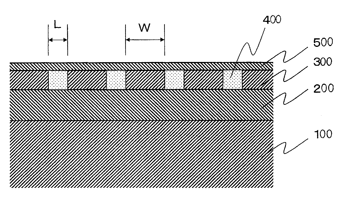
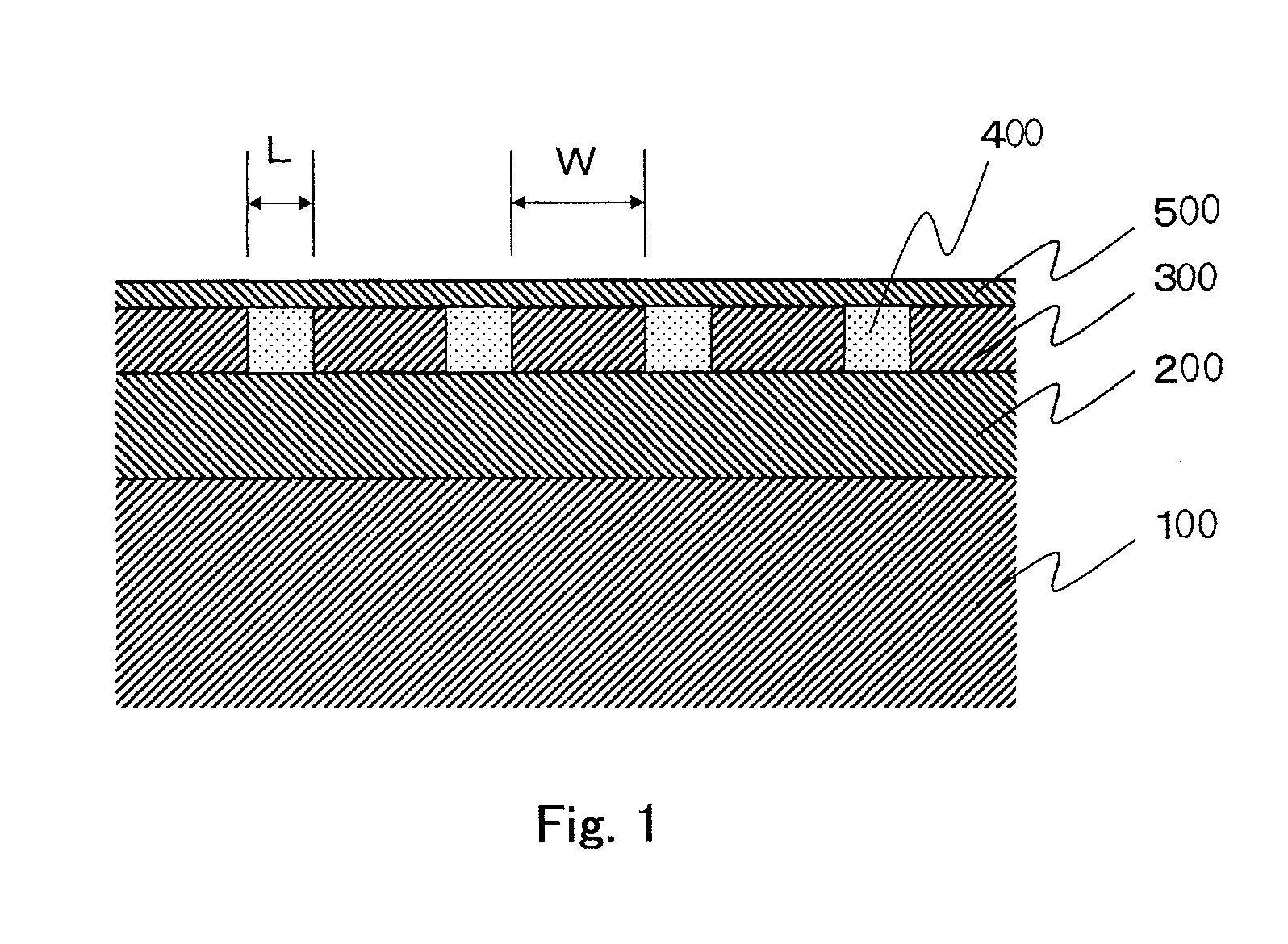
[0134]A glass substrate for HD was placed in a vacuum chamber and the chamber was vacuumed to a pressure of not higher than 1.0×10⁻⁵ Pa to remove the air. The glass substrate used was comprised of glass ceramics having a composition of Li2Si2O5, Al2O3—K2O, Al2O3—K2O, MgO—P2O5 and Sb2O3—ZuO, and has an outer diameter of 65 mm and an inner diameter of 20 mm, and an average surface roughness (Ra) of 2 angstroms.

[0135]On the glass substrate, a soft magnetic underlayer composed of Fe—Co—B, an intermediate layer composed of Ru and a magnetic layer composed of 70Co-5Cr-15Pt-10SiO2 alloy (the numerals immediately before the elements indicate percents by mole of the elements) were formed in this order by DC sputtering. A carbon layer was formed on the magnetic layer by a P-CVD method.

[0136]The respective layers had the following thicknesses. FeCoB soft magnetic underlayer: 60 nm, Ru intermediate layer: 10 nm, and magnetic layer: 15 nm. The carbon layer had a thickness of 40 nm in Example 1, ...

example 7

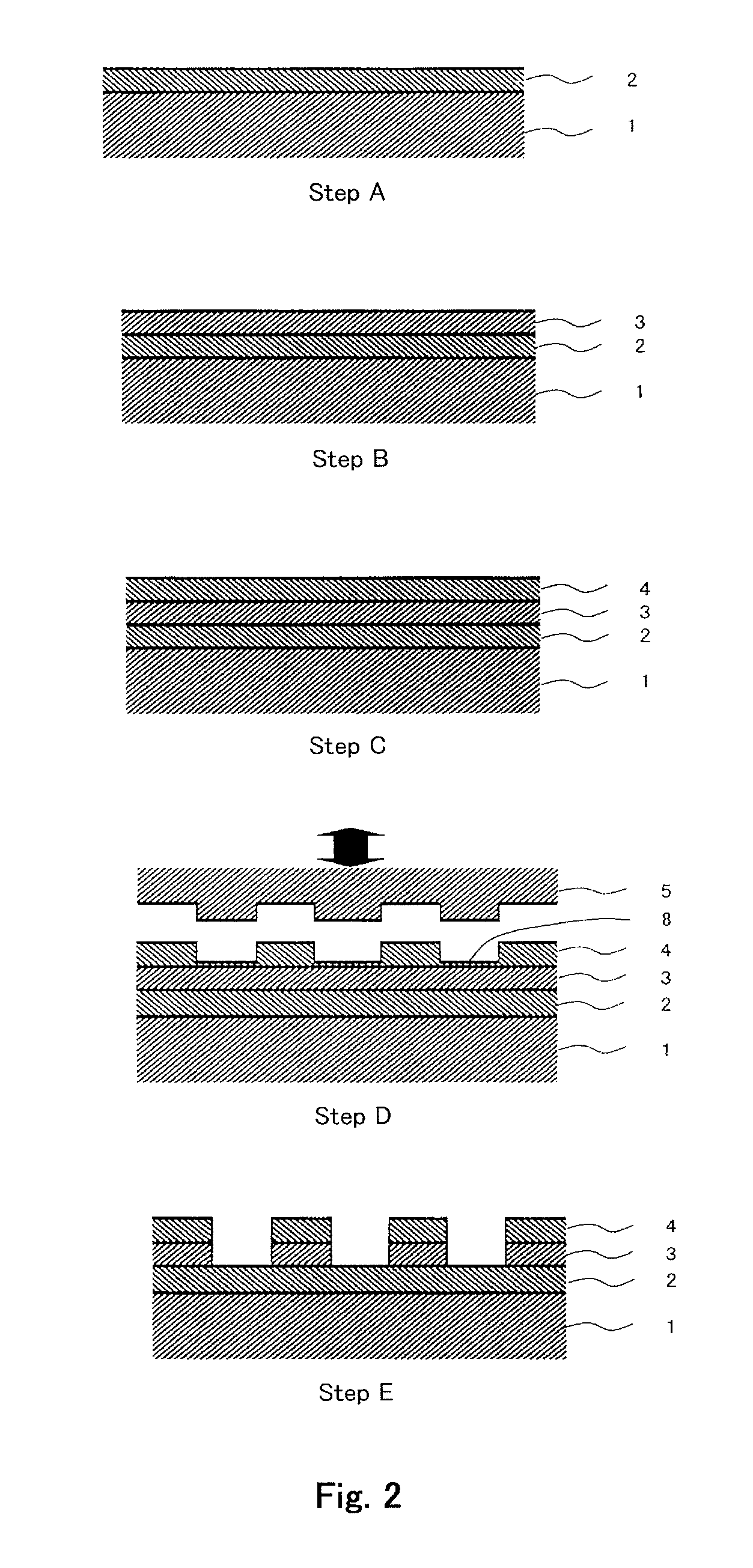
[0142]By the same procedures as described in Example 1, a magnetic recording medium was produced wherein, after the formation of the depressed regions with a depth of about 10 nm in the magnetic layer, but before the removal by dry etching of the residual portions of resist layer and the residual portions of carbon layer, the exposed surface of the magnetic layer was subjected to exposure treatment with CF4 gas at a flow rate of 10 sccm and a pressure of 0.5 Pa for 5 seconds, and successively to exposure treatment with O2 gas at a flow rate of 10 sccm and a pressure of 0.5 Pa for 5 seconds. All other conditions remained the same. The results of 3T-squash measurement are shown in Table 1.


PUM

PropertyMeasurementUnit
thicknessaaaaaaaaaa
thicknessaaaaaaaaaa
depthaaaaaaaaaa

Abstract

A method for producing a magnetic recording medium having a magnetically partitioned magnetic recording pattern on a surface of a nonmagnetic substrate, which comprises the following steps. Step (A) of forming a magnetic layer on a non-magnetic substrate, step (B) of forming a carbon layer on the magnetic layer, step (C) of forming a resist layer on the carbon layer, step (D) of forming a negative pattern of magnetic recording pattern on the resist layer, step (E) of removing the portions of resist layer and carbon layer in regions corresponding to the negative pattern, step (F) of removing at least a surface layer portion of the magnetic layer in the regions corresponding to the negative pattern, and optional step (G) of removing the residual resist layer and carbon layer. The produced magnetic recording medium has a recording / reproducing property equal to or better than conventional ones and exhibits a high recording density.

Description

TECHNICAL FIELD[0001]This invention relates to a process for producing a magnetic recording medium used for a magnetic recording / reproducing apparatus such as a hard disk apparatus. It further relates to the magnetic recording / reproducing apparatus.BACKGROUND ART[0002]In recent years, magnetic recording apparatuses such as a magnetic disk apparatus, a flexible disk apparatus and a magnetic tape apparatus are widely used with their importance being increasing. Recording density of a magnetic recording medium used in the magnetic recording apparatus is greatly enhanced. Especially, since the development of MR head and PRML technique, the areal recording density is more and more increasing. Recently GMR head and TMR head have been developed, and the rate of increase in the areal recording density is about 100% per year. There is still increasing a demand for further enhancing the recording density, and therefore, a magnetic layer having a higher coercive force, and a higher signal-to-n...

Claims


Application Information

Patent Timeline
Patent Type & Authority Applications(United States)
IPC IPC(8): G11B21/02B05D5/12
CPCH01F41/34G11B5/855
Inventor FUKUSHIMA, MASATOSAKAWAKI, AKIRAYAMANE, AKIRA
Owner SHOWA DENKO KK
Why Eureka
Try Eureka