
Process for making magnetic recording medium and magnetic recording-reproducing apparatus

a recording medium and recording technology, applied in the field of making magnetic recording medium and recording recording apparatus, can solve the problems of reducing the bit error rate, affecting the enhancement of the recording density, and reducing the minimum magnetization volume per bit, etc., to achieve good head-floatability, high recording density, and excellent partitionability

Active Publication Date: 2012-12-25
RESONAC CORPORATION
View PDF12 Cites 2 Cited by
  • Summary
  • Abstract
  • Description
  • Claims
  • Application Information

AI Technical Summary

Benefits of technology

[0048]According to the present invention, a magnetic recording medium is made in an industrially advantageous manner by a process wherein a magnetic recording pattern is formed after a magnetic layer is formed on a non-magnetic substrate. The resulting magnetic recording medium is characterized in that the magnetic recording pattern is partitioned by the regions exhibiting excellent partitionability and the signal interferes occurring between the adjacent regions in the pattern are suppressed, and further that the high recording density can be achieved.
[0049]The magnetic recording medium produced by the process of the present invention has a flat and smooth surface and exhibits a good head-floatability at a low floating height.

Problems solved by technology

However, with an increase of the track density, magnetic recording information is liable to inferring with each other between adjacent tracks, and magnetization transition regions in the boundary regions thereof as noise source tend to impair the SNR.
These problems result in lowering in bit error rate and impede the enhancement of the recording density.
However, when the bit size is decreased, the minimum magnetization volume per bit becomes small, and the recorded data are tend to disappear due to magnetization reversal caused by heat fluctuation.
This operation is advantageous in that the influence of the adjacent tracks can be minimized, but disadvantageous in that the reproduction power is rather low.
This also leads to difficulty in enhancement of the SNR to a desired level.
The fabrication of the surface for the formation of patterned tracks is carried out on the once-formed magnetic recording medium, and therefore, has problems such that the magnetic recording medium is liable to be stained in the fabrication course, and the fabrication process is complicated.
This method does not have the problem of being stained in the fabrication course, but, has a problem such that the pattern with protrusions and depressions, formed on a substrate, influences the surface configuration of the layers formed thereon, and therefore, it influences the stability in floating state of a floating recording-reproducing head and in height of floatation.
However, the above-mentioned discrete tack method utilizing modification of regions partitioning magnetic tracks has a problem such that the magnetic layer tends to be damaged by ion implantation or laser irradiation, and further that, although an ion implantation or laser irradiation with high energy is applied, its energy density over the entire magnetic recording medium is low and the time required for achieving the desired degree of modification is long.Patent document 1 JP 2004-164692 A1Patent document 2 JP 2004-178793 A1Patent document 3 JP 2004-178794 A1Patent document 4 JP H5-205257 A1Patent document 5 JP 2006-209952 A1Patent document 6 JP 2006-309841 A1

Method used


Image

  • Process for making magnetic recording medium and magnetic recording-reproducing apparatus
  • Process for making magnetic recording medium and magnetic recording-reproducing apparatus
  • Process for making magnetic recording medium and magnetic recording-reproducing apparatus

Examples


example 1

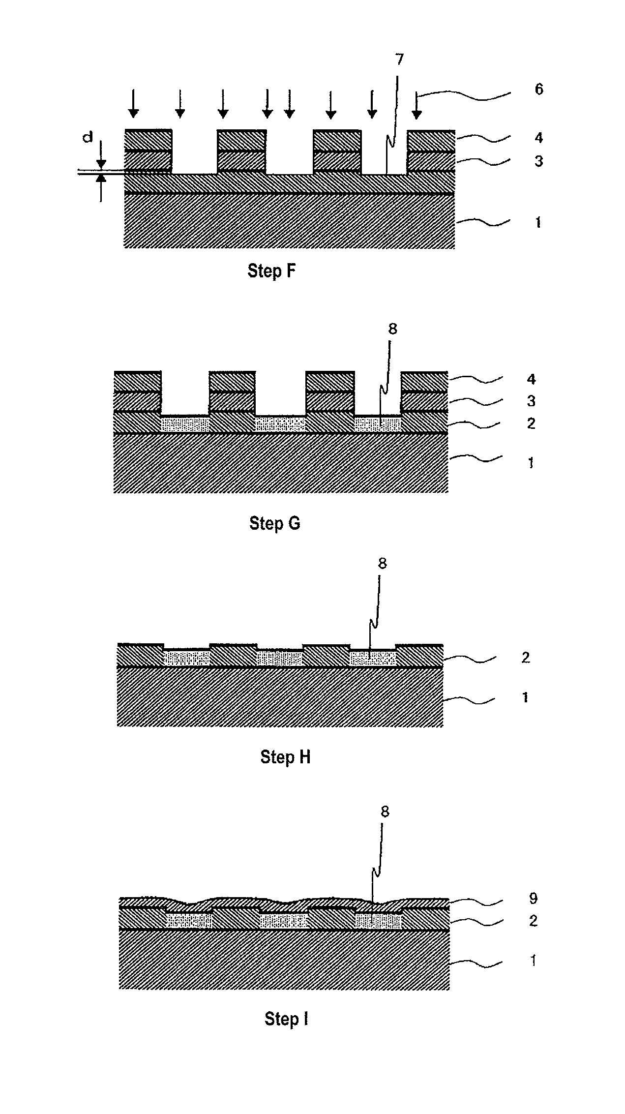
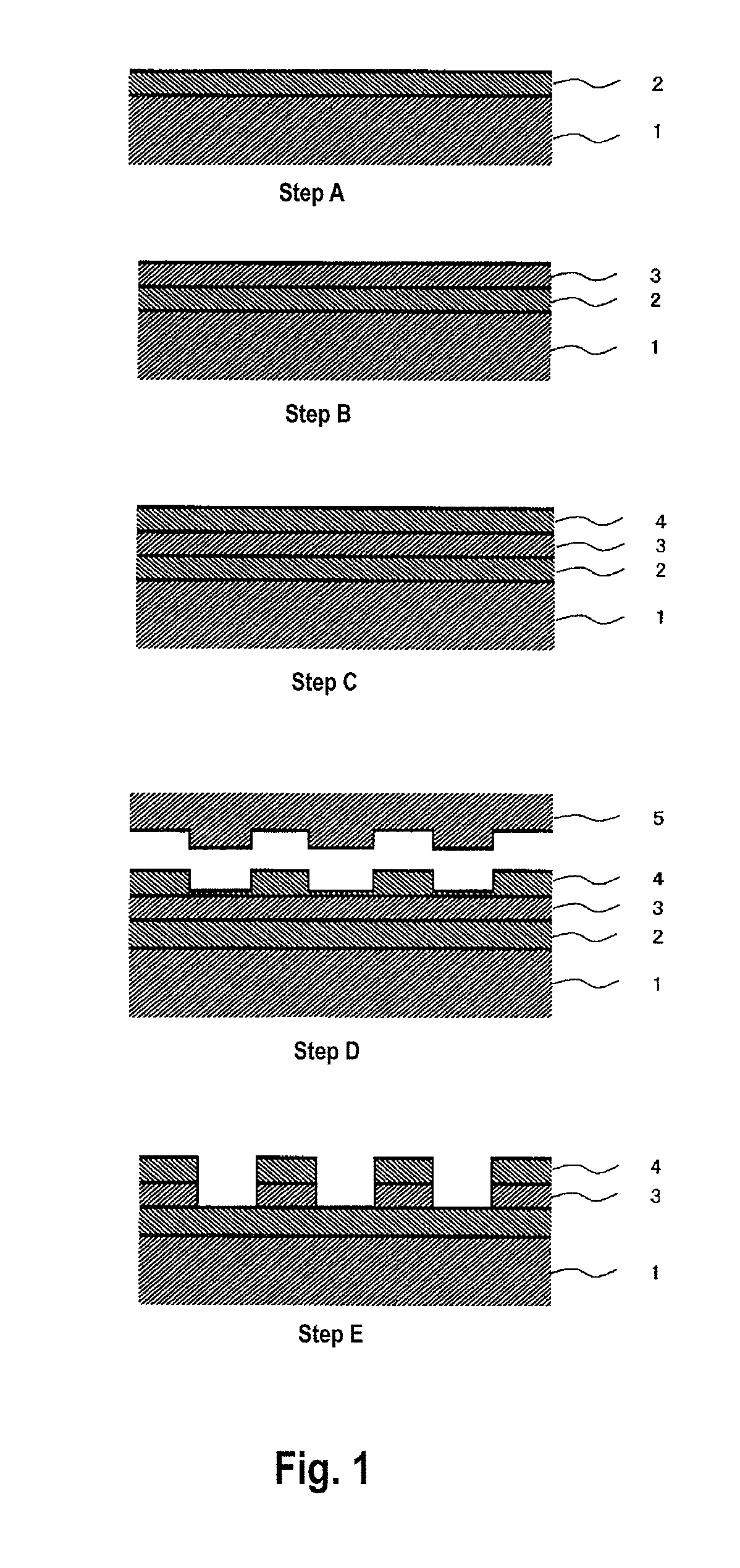
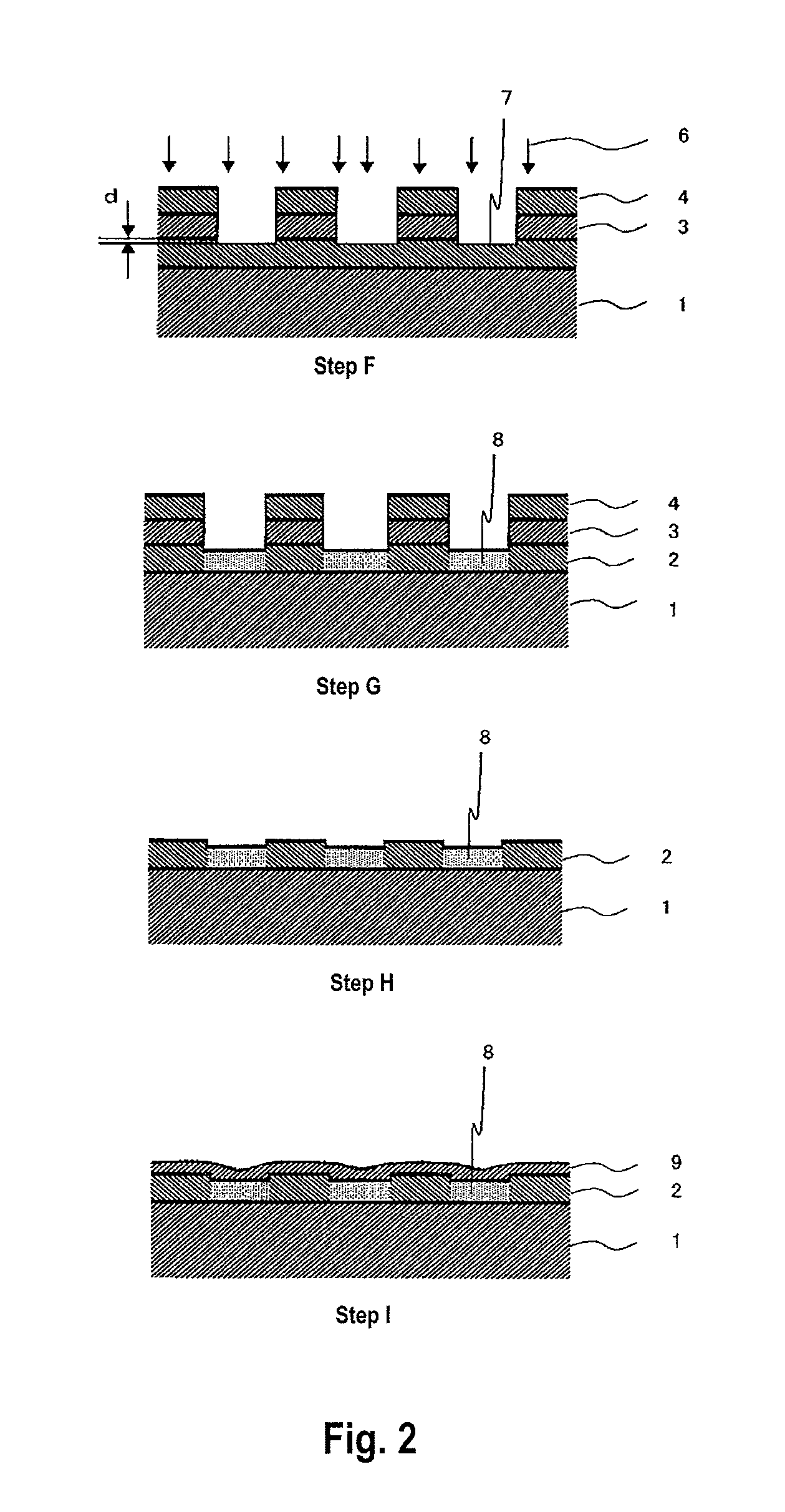
[0143]A glass substrate for HD was placed in a vacuum chamber and the chamber was vacuumed to a pressure of not higher than 1.0×10⁻⁵ Pa to remove the air. The glass plate used is comprised of glass ceramics having a composition of Li2Si2O5, Al2O3—K2O, Al2O3, —K2O, MgO—P2O5 and Sb2O3—ZuO, and has an outer diameter of 65 mm and an inner diameter of 20 mm, and an average surface roughness (Ra) of 2 angstroms.

[0144]On the glass substrate, a soft magnetic layer composed of FeCoB, an intermediate layer composed of Ru and a magnetic layer composed of 70Co-5Cr-15Pt-10SiO2 alloy were formed in this order by DC sputtering. The thicknesses of respective layers are: FeCoB soft magnetic layer: 600 angstroms, Ru intermediate layer: 100 angstroms and magnetic layer: 150 angstroms.

[0145]A masking layer composed of Ta with a thickness of 60 nm was formed on the laminated structure by sputtering. Then a resist layer composed of ultraviolet ray-curable novolak resin with a thickness of 100 nm was form...

examples 2 to 11

[0151]By substantially the same procedures and conditions as employed in Example 1, magnetic recording mediums were made wherein the milling depth of the magnetic layer (i.e., the thickness of the removed surface layer portions of the magnetic layer) was changed as shown in Table 1, below. All other conditions remained the same. The making conditions employed are shown in Table 1.


PUM

PropertyMeasurementUnit
thicknessaaaaaaaaaa
Raaaaaaaaaaa
Raaaaaaaaaaa

Abstract

Provided is a process for making a magnetic recording medium having a magnetically partitioned magnetic recording patterns, which comprises the following three steps (1), (2) and (3), conducted in this order: (1) a step of forming a magnetic layer on a non-magnetic substrate; (2) a step of removing surface layer portions of regions for magnetically partitioning the magnetic layer; and (3) a step of exposing the thus-exposed regions of the magnetic layer, from which the surface layer portions have been removed, to a reactive plasma or a reactive ion, to modify the magnetic characteristics of the regions of magnetic layer, whereby a magnetic recording pattern is formed which are magnetically partitioned by the regions of magnetic layer having the modified characteristics. Thus, a magnetic recording medium having an enhanced recording density and minimizing letter bleeding at writing can be made with a high efficiency.

Description

TECHNICAL FIELD[0001]This invention relates to a process for making a magnetic recording medium used for a magnetic recording-reproducing apparatus such as a hard disk apparatus.BACKGROUND ART[0002]In recent years, magnetic recording apparatuses such as a magnetic disk apparatus, a flexible disk apparatus and a magnetic tape apparatus are widely used with their importance being increasing. Recording density of a magnetic recording medium used in the magnetic recording apparatus is greatly enhanced. Especially, since the development of MR head and PRML technique, the areal recording density is more and more increasing. Recently GMR head and TMR head have been developed, and the rate of increase in the areal recording density is about 100% per year. There is still increasing a demand for further enhancing the recording density, and therefore, a magnetic layer having higher coercive force, and a higher signal-to-noise ratio (SNR) and a high resolution are eagerly desired.[0003]An attem...

Claims


Application Information

Patent Timeline
Patent Type & Authority Patents(United States)
IPC IPC(8): G11B5/127H04R31/00
CPCB82Y10/00G11B5/743G11B5/746G11B5/82G11B5/855Y10T29/49032G11B5/865Y10T29/4903Y10T29/49025
Inventor FUKUSHIMA, MASATOSAKAWAKI, AKIRAYAMANE, AKIRA
Owner RESONAC CORPORATION
Learn More