Staggered laser-etch line graphic system, method and articles of manufacture

a laser etching and line graphic technology, applied in adaptive control, process and machine control, instruments, etc., can solve the problems of difficulty in applying detailed or complex laser etching graphic designs in craft-based methods of manufacturing, difficulty in reducing the visual impact of demarcation lines, and difficulty in reducing demarcation lines.

Inactive Publication Date: 2010-10-28
REVOLAZE LLC
View PDF32 Cites 62 Cited by
  • Summary
  • Abstract
  • Description
  • Claims
  • Application Information

AI Technical Summary

Benefits of technology

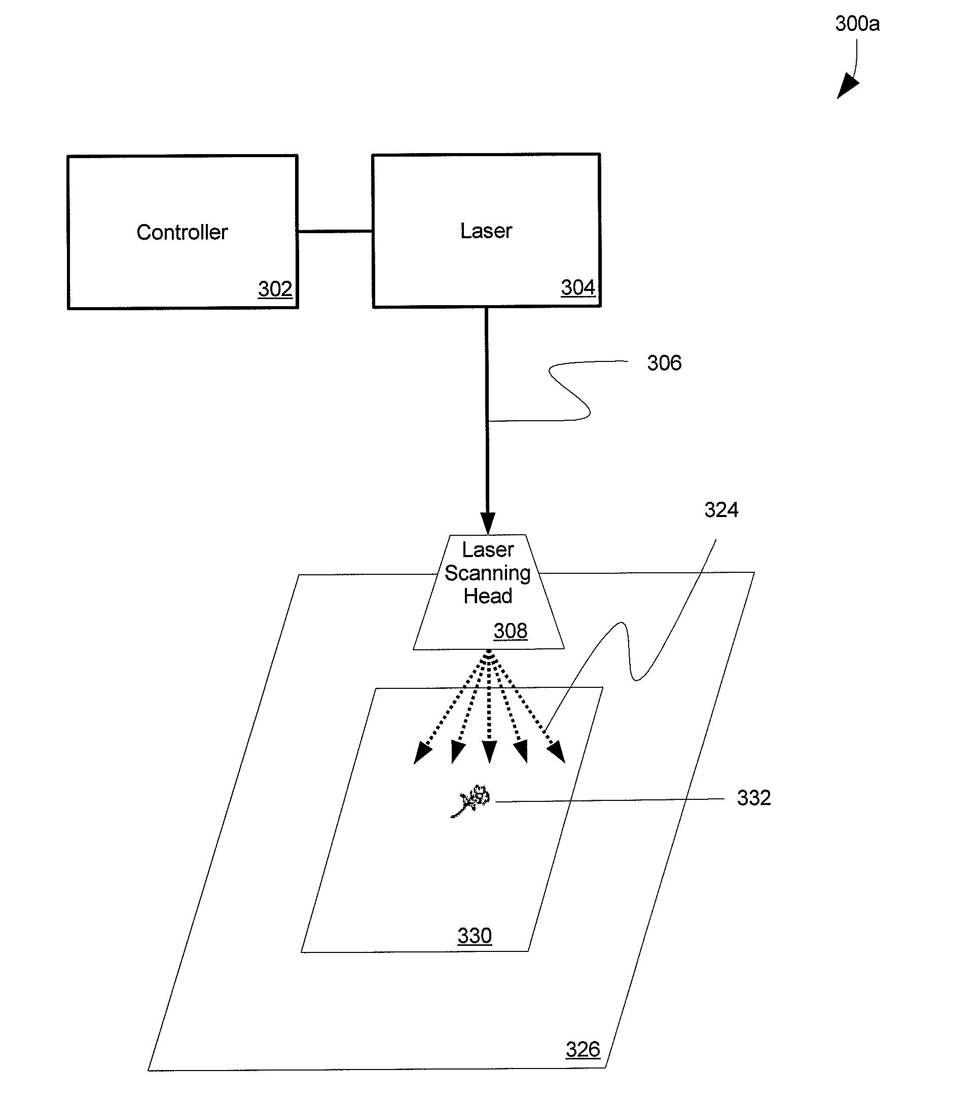
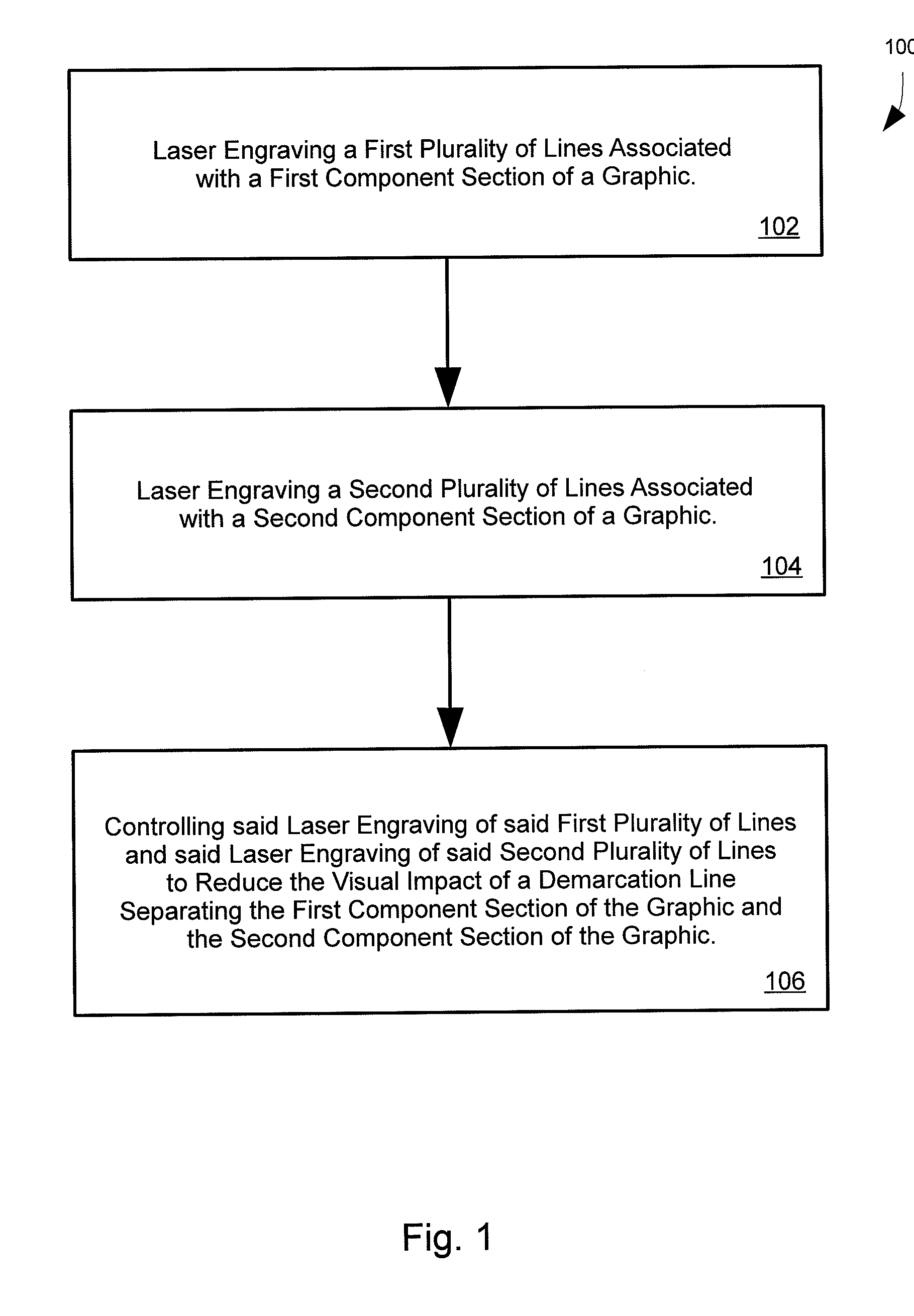
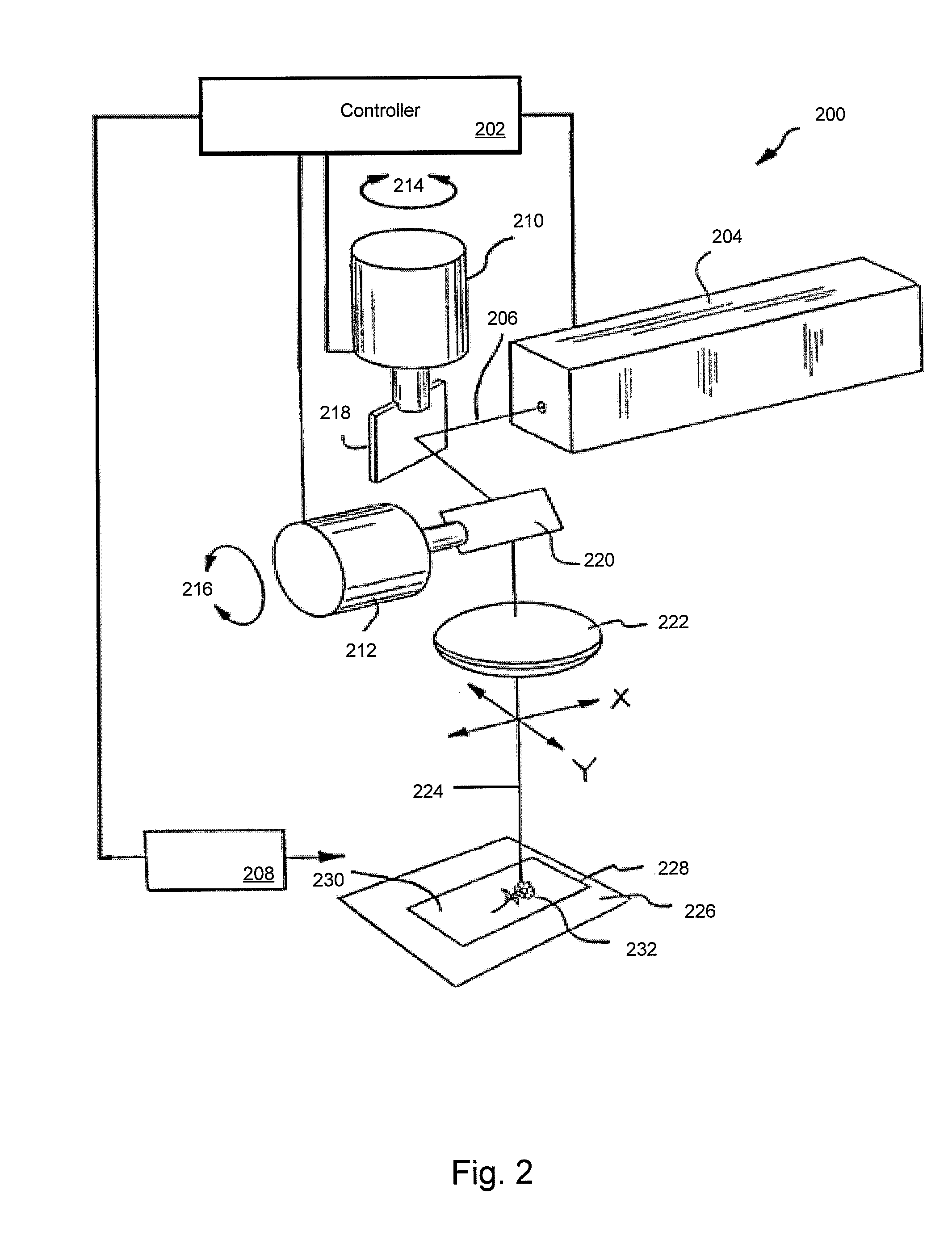
[0007]A first aspect of the invention provides a method for reducing a visual impact of a demarcation line of a graphic, the method comprising laser engraving a first plurality of lines associated with a first component section of a graphic on a surface of an article; laser engraving a second plurality of lines associated with a second component section of the graphic on the surface of the article; and controlling said first plurality of lines and said second plurality of lines to reduce the visual impact of a demarcation line separating the first component section of the graphic and the second component section of the graphic.

Problems solved by technology

One of the difficulties associated with the laser etching of a graphic design over a substantial surface area is that laser etching equipment is typically not capable of etching a large detailed graphic design in a single unitary application of the whole graphic over the surface on an article.
This difficulty is particularly acute when the articles of manufacture are mass-produced in a repeating process or a continuous process such as an extrusion process.
To some extent the difficulties in applying a detailed or complex laser etched graphic design can also occur in craft-based methods of manufacturing.
A problem can arise in the context of joining the component sections during the laser etching process to form a unitary image of a whole graphic design, particularly for relatively large work pieces that have a visible area exceeding the field size of the laser.
This problem typically arises in the application of joined graphic designs as the meeting point will involve a visually perceptible imperfection forming a notable demarcation line between the two component sections of the graphic design when applied by laser etching.
The demarcation is a substantial problem as it detracts from the overall aesthetic quality of the manufactured article.

Method used


Image

  • Staggered laser-etch line graphic system, method and articles of manufacture
  • Staggered laser-etch line graphic system, method and articles of manufacture
  • Staggered laser-etch line graphic system, method and articles of manufacture

Examples


Embodiment Construction

)

[0042]Reference will now be made in detail to exemplary embodiments and methods of the invention as illustrated in the accompanying drawings, in which like reference characters designate like or corresponding parts throughout the drawings. It should be noted, however, that the invention in its broader aspects is not limited to the specific details, representative devices and methods, and illustrative examples shown and described in this section in connection with the exemplary embodiments and methods. The invention according to its various aspects is particularly pointed out and distinctly claimed in the attached claims read in view of this specification, and appropriate equivalents.

[0043]The terms “laser” and “laser beam” may be used interchangeably. The terms “mark” and “scribe” are used interchangeably herein, and as used mean to irradiate an article or component, such as a board made of plastic lumber, with a laser to form a graphic design, such as a wood grain image. In the co...


PUM

PropertyMeasurementUnit
widthaaaaaaaaaa
weight percentaaaaaaaaaa
angleaaaaaaaaaa

Abstract

A staggered laser-etch line graphic system, method, and articles of manufacture are provided. One described method includes the steps of laser engraving a first plurality of lines associated with a first component section of a graphic on a surface of an article; laser engraving a second plurality of lines associated with a second component section of the graphic on the surface of the article; and controlling said laser engraving of the first plurality of lines and said laser engraving of second plurality of lines to reduce the visual impact of a demarcation line separating the first component section of the graphic and the second component section of the graphic.

Description

CROSS-REFERENCE TO RELATED APPLICATIONS AND CLAIM TO PRIORITY[0001]This patent application claims the benefit of U.S. Provisional Application No. 61 / 172,893, entitled “Staggered Laser-Etch Line Graphic System, Method and Articles of Manufacture,” and filed Apr. 27, 2009, the entirety of which is incorporated herein and to which priority is claimed.FIELD OF THE INVENTION[0002]The present invention relates to laser engraving graphics onto article surfaces, and more particularly to a staggered laser-etch line graphic system, method, and articles of manufacture.BACKGROUND OF THE INVENTION[0003]Manufactured articles can present large or substantial viewable surface areas. Often it is desirable to apply a graphic design to one or more of these surface areas. Graphic designs include ordered patterns, random non-patterns, discrete simple graphic elements, complex graphical images and the like. Printing, painting, and engraving are just a few examples of techniques that may be employed to ap...

Claims


Application Information

Patent Timeline
Patent Type & Authority Applications(United States)
IPC IPC(8): B32B3/10B23K26/38
CPCB23K26/0807B23K26/367Y10T428/24802G05B13/00Y10T428/24479B44C1/228B23K26/364B23K26/082B23K26/355
Inventor COSTIN, JR., DARRYL J.
Owner REVOLAZE LLC
Why Eureka
Try Eureka