Self-Flaring Active Fixation Element for a Stent Graft

a technology of active fixation element and stent graft, which is applied in the field of active structure for fixing endoluminal stent graft, can solve the problems of excess bulging and damage to the body vessel, the surface area available to resist the outward radial force of the stent graft, and the inability to firmly and permanently affix the stent graft. to the inside of the body vessel, so as to achieve the effect of reducing the stress

Active Publication Date: 2010-10-28
MEDTRONIC VASCULAR INC
View PDF11 Cites 105 Cited by
  • Summary
  • Abstract
  • Description
  • Claims
  • Application Information

AI Technical Summary

Benefits of technology

[0015]During expansion at deployment, the large amount of strut material at the surface facing the adjacent strut and the neutral bending axes of the adjacent struts and their connection to the a common apex (at one end of the strut resists deformation more than the relatively smaller amount of strut material away from the center of the apex, thereby effecting the outward twist of the struts and the upper apexes, and the hooked fixation elements coupled thereto. The struts and upper apexes strain and deform by twisting to redistribute and lower the stress induced in the struts during radial expansion of the stent graft. The degree of apical twisting is controlled by adjusting the diagonal angle α of the strut's inner laser cut surface at the side of strut facing the adjacent strut extending from a common apex.
[0016]By making the angle α of the stent diagonal surface with respect to the apex centerline, the apex will rotate as a result of being tied at an angle to a common apex and as a result of the geometric orientation of the cross-sectional area which is subject to stress and deformation as deployment takes place. The additional material in the inner portion of the strut (along its longest surface) resists deformation more than the material at the outer edge of the strut and apex relative to the angle of the diagonal cut establishing the angle with respect to a radius of the stent graft facilitating the rotation of the apex upon expansion. By attaching the struts to the apex it can rotate with its hook to impinge the vessel wall. The hook also folds into the confines of the projection of the wall thickness of the hollow cylindrical wall defined by the stent ring when in it is constrained.
[0017]Accordingly, use of a stent graft including self-flaring (self rotating)active fixation elements, provides secure fixation of the stent graft to the body vessel by both passive and active means. Also provided is a controlled radial biasing force by the spring attachment element and hooked and / or spiked fixation elements that present no impediment to the smooth intraluminal deployment of the stent graft.

Problems solved by technology

A body vessel's capacity to resist a continuous outward radial force is limited.
Excessive outward radial force on the interior wall of a body vessel could cause excess bulging and damage to the body vessel.
Also, in cases where the contact interface, sometimes called the landing zone, between the stent graft and the body vessel is small (short), the surface area on the interior of the body vessel available to resist outward radial force of the stent graft may be insufficient to firmly and permanently affix the stent graft.
However, with this second approach it is often difficult to contain the laterally extending fixation elements within a conventional flexible sheath, well known to those of skill in the art, used for containing a compressed stent graft prior to deployment.

Method used


Image

  • Self-Flaring Active Fixation Element for a Stent Graft
  • Self-Flaring Active Fixation Element for a Stent Graft
  • Self-Flaring Active Fixation Element for a Stent Graft

Examples


Embodiment Construction

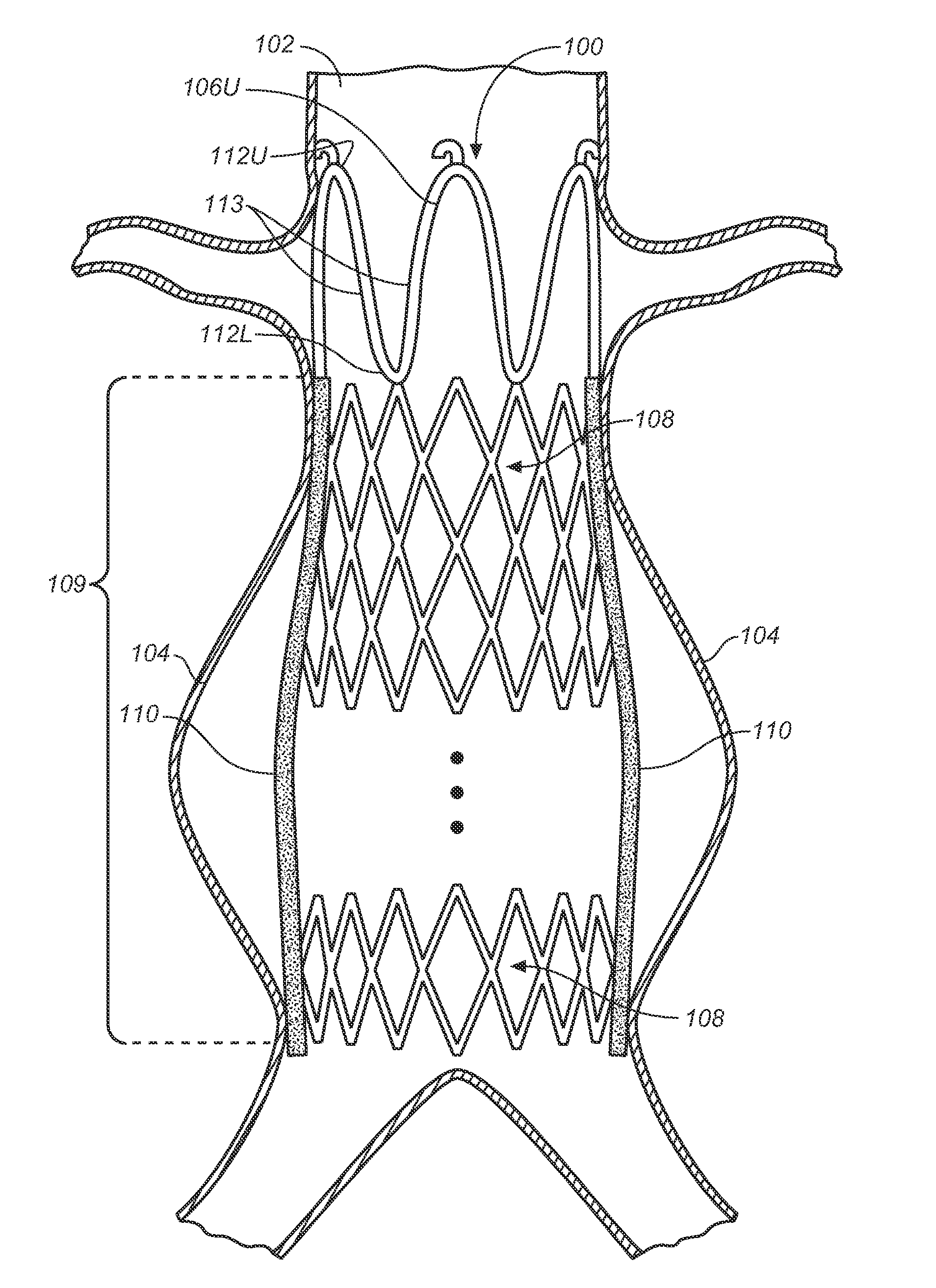
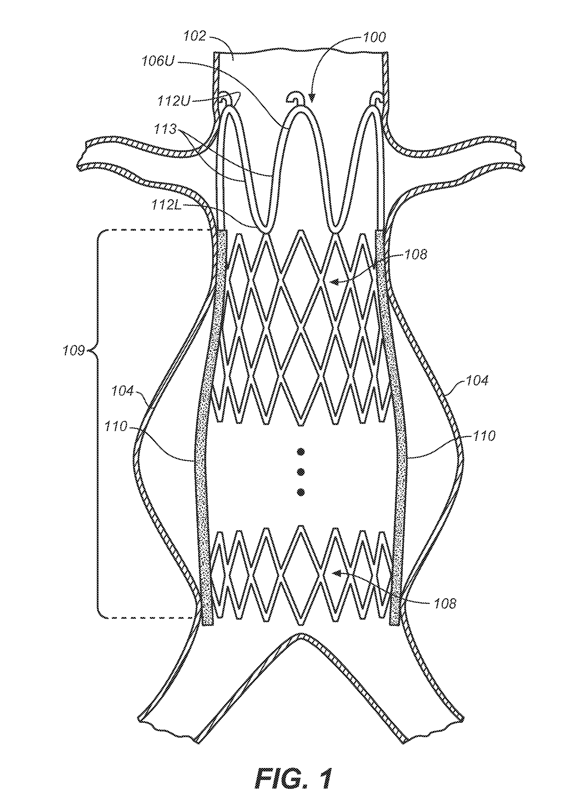
[0028]FIG. 1 is a schematicized partial cutaway view of a body vessel 102 containing an aneurysm 104 excluded from body vessel 102 by a deployed stent graft 100 configured in accordance with the present invention.

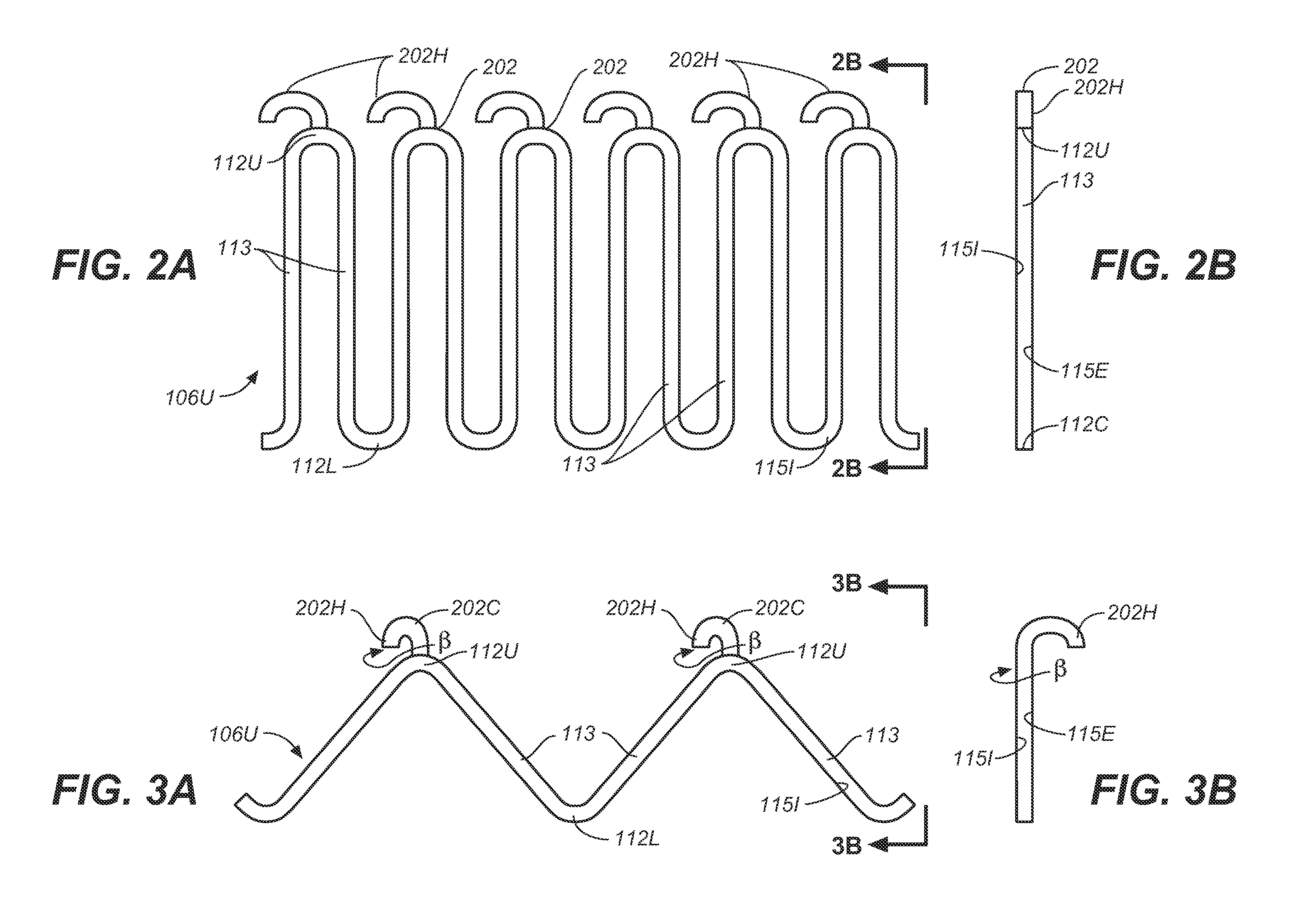
[0029]FIG. 2A is a schematicized before deployment flat-layout view and FIG. 2D is a schematicized perspective view of an upper spring attachment element 106U of stent graft 100 including self-flaring, active, hooked fixation elements 202. In use, stent graft 100 is generally configured in a tubular shape but, in FIG. 2A, upper spring attachment element 106U is shown in unfurled or flat-layout view for clarity of presentation.

[0030]FIG. 2B is a schematicized before deployment end view in the direction of 2B-2B of upper spring attachment element 106U shown in FIG. 2A.

[0031]FIG. 2C is a schematicized before deployment top plan view of one upper apex 112U of the upper spring attachment element 106U of FIGS. 2A and 2B. FIG. 2E is a schematicized side view of the of the upper ap...


PUM

PropertyMeasurementUnit
structureaaaaaaaaaa
angleaaaaaaaaaa
radiusaaaaaaaaaa

Abstract

A stent graft includes a stent graft material of tubular shape and annular shaped stent elements coupled to the stent graft material. The stent graft further includes hooked fixation elements, having hook-end portions and coupling-end, circumferentially spaced about an annular shaped spring attachment element, and coupled to the stent graft at apexes of the spring attachment element. Before deployment the hook-end portions of the apexes of the attachment element and the hooked fixation elements attached thereto are compressed within the space bounded by the interior and exterior sides of the spring attachment element and angled laser cut strut inner surfaces under each apex of the spring attachment element are cut at an angle to cause apex and hook rotation at expansion and deployment. At deployment, the apex and hook-end portions rotate outwardly from the stent graft, partially penetrating the body vessel walls in which the stent graft is deployed and actively fixing the stent graft at the position of deployment.

Description

FIELD OF THE INVENTION[0001]The present invention relates generally to endoluminal stent grafts and more particularly to an active structure for fixing endoluminal stent grafts within body vessels.BACKGROUND OF THE INVENTION[0002]A stent graft typically includes radially expandable stents, a plurality of annular stent rings forming a cylindrical reinforcement structure, and a cylindrically shaped graft material to which the stent rings are coupled. Stent grafts are well known to be used in acting as reinforced grafts which are delivered by a catheter and deployed to bypass a damaged diseased portion of an arterial body vessel (lumen).[0003]At deployment, after insertion and transluminal transport to the point of use within a damaged or diseased body vessel, e.g., an aneurysmal location in an artery, the stent graft is radially expanded. A stent graft is typically self-expanding or balloon expandable by application of pressure applied outwardly from the interior of the stent graft. A...

Claims


Application Information

Patent Timeline
Patent Type & Authority Applications(United States)
IPC IPC(8): A61F2/06B23P11/00
CPCA61F2/07A61F2002/061A61F2002/8483A61F2002/8486Y10T29/49826A61F2/90A61F2230/0019A61F2220/0016A61F2230/0026A61F2/89
Inventor RUST, MATTHEW
Owner MEDTRONIC VASCULAR INC
Why Eureka
Try Eureka