Split-cycle engine with dual spray targeting fuel injection

a fuel injection and split-cycle technology, applied in the direction of low-pressure fuel injection, machines/engines, mechanical equipment, etc., can solve the problem of less than optimal fuel delivery, and achieve the effect of improving engine performan

Inactive Publication Date: 2010-11-04
SKADERI GRUP LLC
View PDF26 Cites 6 Cited by
  • Summary
  • Abstract
  • Description
  • Claims
  • Application Information

AI Technical Summary

Benefits of technology

[0024]The present invention provides an apparatus for and method of injecting fuel into an engine wherein spray holes of the engine's fuel injectors are aimed at certain targets to produce fuel sprays that enhance engine performance.

Problems solved by technology

However, various parameters of the fuel injectors 28 and spray hole targeting are critical for assuring the proper delivery of fuel to the expansion cylinder, wherein variations in these parameters can result in less than optimal fuel delivery.

Method used


Image

  • Split-cycle engine with dual spray targeting fuel injection
  • Split-cycle engine with dual spray targeting fuel injection
  • Split-cycle engine with dual spray targeting fuel injection

Examples


Embodiment Construction

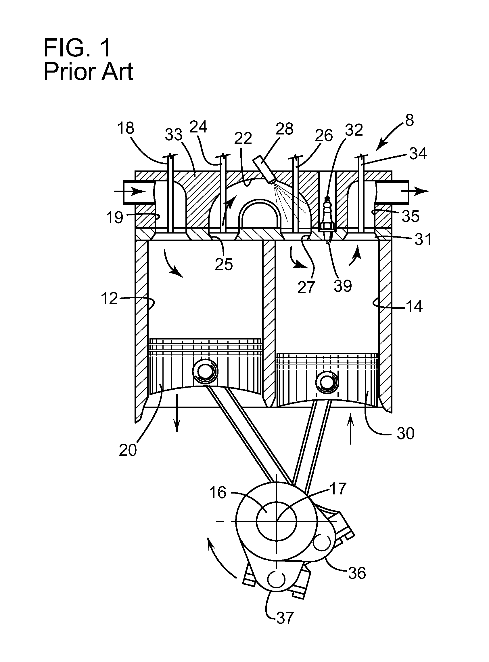
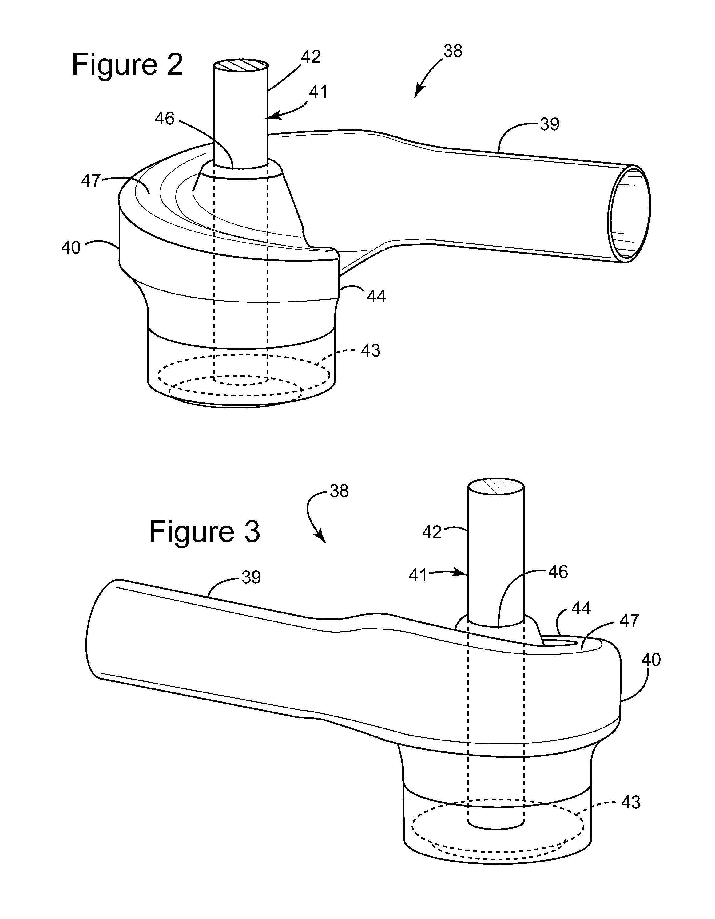
[0060]Referring to FIGS. 2 and 3, for purposes of clarity, a helical passage 38 (as referred to herein) is a connecting passage (port), which typically links an inlet manifold to an inlet valve of a cylinder head in a conventional engine. The downstream portion of the helical passage 38 includes a generally straight runner section 39 integrally connected to a helical end section 40, which is disposed over an inlet valve 41. The inlet valve 41 includes a stem 42 and a head 43, wherein the head 43 opens to a cylinder (not shown). The flow area within the helical end section 40 is disposed in a circumferential and descending funnel 44 around the valve stem 42, which is carried in a bore 46 of the end section 40. The funnel 44 spirals over at least one-third of a turn, and preferably between one-half and three-quarters of a turn, about the valve stem 42, so that incoming air is forced to rotate about the valve stem 42 prior to entering the cylinder. The roof 47 of the funnel 44 reduces ...


PUM


Abstract

An engine includes a rotatable crankshaft and an expansion piston slidably received within an expansion cylinder and operatively connected to the crankshaft. A crossover passage including walls connects a source of high pressure gas to the expansion cylinder. A crossover expansion (XovrE) valve is operable to control fluid communication between the crossover passage and the expansion cylinder. The XovrE valve includes a valve head and a valve stem extending from the valve head. A fuel injector operable to inject fuel into the crossover passage includes a plurality of spray holes disposed in a nozzle end and aimed at an at least one target at which fuel emitting from the spray holes is directed to form at least one spray pattern. The at least one target is located above a seated position of the XovrE valve head and between the walls of the crossover passage and the XovrE valve stem.

Description

CROSS REFERENCE TO RELATED APPLICATION[0001]This application claims the benefit of U.S. Provisional Application No. 61 / 215,146, filed May 1, 2009 and titled: Split-Cycle Engine with Dual Spray Targeting Fuel Injection.TECHNICAL FIELD[0002]The present invention relates to internal combustion engines. More specifically, the present invention relates to a split-cycle engine having fuel injectors which produce dual spray patterns.BACKGROUND OF THE INVENTION[0003]For purposes of clarity, the term “conventional engine” as used in the present application refers to an internal combustion engine wherein all four strokes of the well-known Otto cycle (the intake, compression, expansion and exhaust strokes) are contained in each piston / cylinder combination of the engine. Each stroke requires one half revolution of the crankshaft (180 degrees crank angle (CA)), and two full revolutions of the crankshaft (720 degrees CA) are required to complete the entire Otto cycle in each cylinder of a convent...

Claims


Application Information

Patent Timeline
Patent Type & Authority Applications(United States)
IPC IPC(8): F02B3/00F02B33/22F02B25/00F02B31/00
CPCF02B3/02F02B31/02F02B31/082F02B33/22F02F1/4228F02B2023/108F02M69/044Y02T10/146F02B33/44F02B2023/103F02F1/4235Y02T10/12F02B75/20F02M61/18F02M61/14
Inventor PHILLIPS, FORD
Owner SKADERI GRUP LLC
Why Eureka
Try Eureka