Flow channel switching valve

a technology of flow channel and switching valve, which is applied in the direction of valve operating means/release devices, instruments, mechanical equipment, etc., can solve the problems of insufficient power of the motor for rotating the rotor to switch the flow channel, unevenness aggravating the surface abrasion, and various malfunctions, so as to prevent the increase of the torque of the rotor, the effect of reducing the abrasion on the rotor brought by the surface of the stator and improving the contact plan

Inactive Publication Date: 2010-11-04
SHIMADZU CORP
View PDF9 Cites 21 Cited by
  • Summary
  • Abstract
  • Description
  • Claims
  • Application Information

AI Technical Summary

Benefits of technology

[0019]Carbon particulate blocks on the surface of the DLC coating can be removed by polishing, so as to improve the slidability on the contact planes of the rotor and the stator and prevent the torque of the rotor from being increased. The abrasion on the rotor brought by the surface of the stator is reduced, so that the flow channel switching valve can be stably used for a long time, thereby avoiding the column deterioration or piping blockage resulted from chippings produced by the rotor. Besides, by maintaining the close contact between the contact planes of the rotor and the stator, the liquid leakage is prevented, and flow channels are switched reliably without cross contamination.

Problems solved by technology

If the part that should be a smooth plane has such unevenness, various malfunctions occur.
If the sliding counterpart (rotor) is resin, the unevenness aggravates the abrasion of the surface.
Besides, since the stator surface and the rotor surface are pressed to rotate under a large force, if the unexpected friction is produced due to the surface unevenness, the power of a motor for rotating the rotor becomes insufficient for switching the flow channels, and as a result, the flow channel switching valve fails to be operated.
If the flow channel switching valve fails to be operated, an entire analysis device for forming the flow channels cannot maintain its normal operation.

Method used


Image

  • Flow channel switching valve
  • Flow channel switching valve
  • Flow channel switching valve

Examples


Embodiment Construction

[0025]Reference will now be made in detail to the present embodiments of the invention, examples of which are illustrated in the accompanying drawings. Wherever possible, the same reference numbers are used in the drawings and the description to refer to the same or like parts.

[0026]The embodiment of the present invention is illustrated below with reference to the drawings.

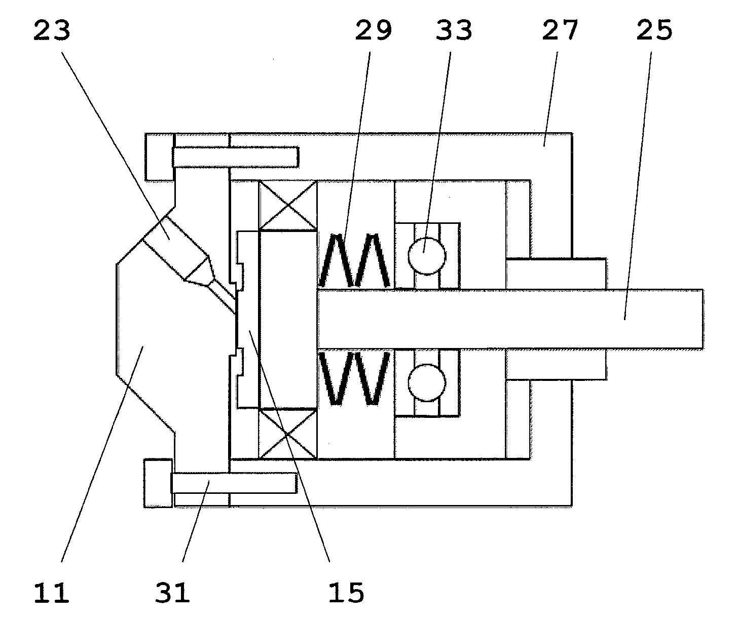
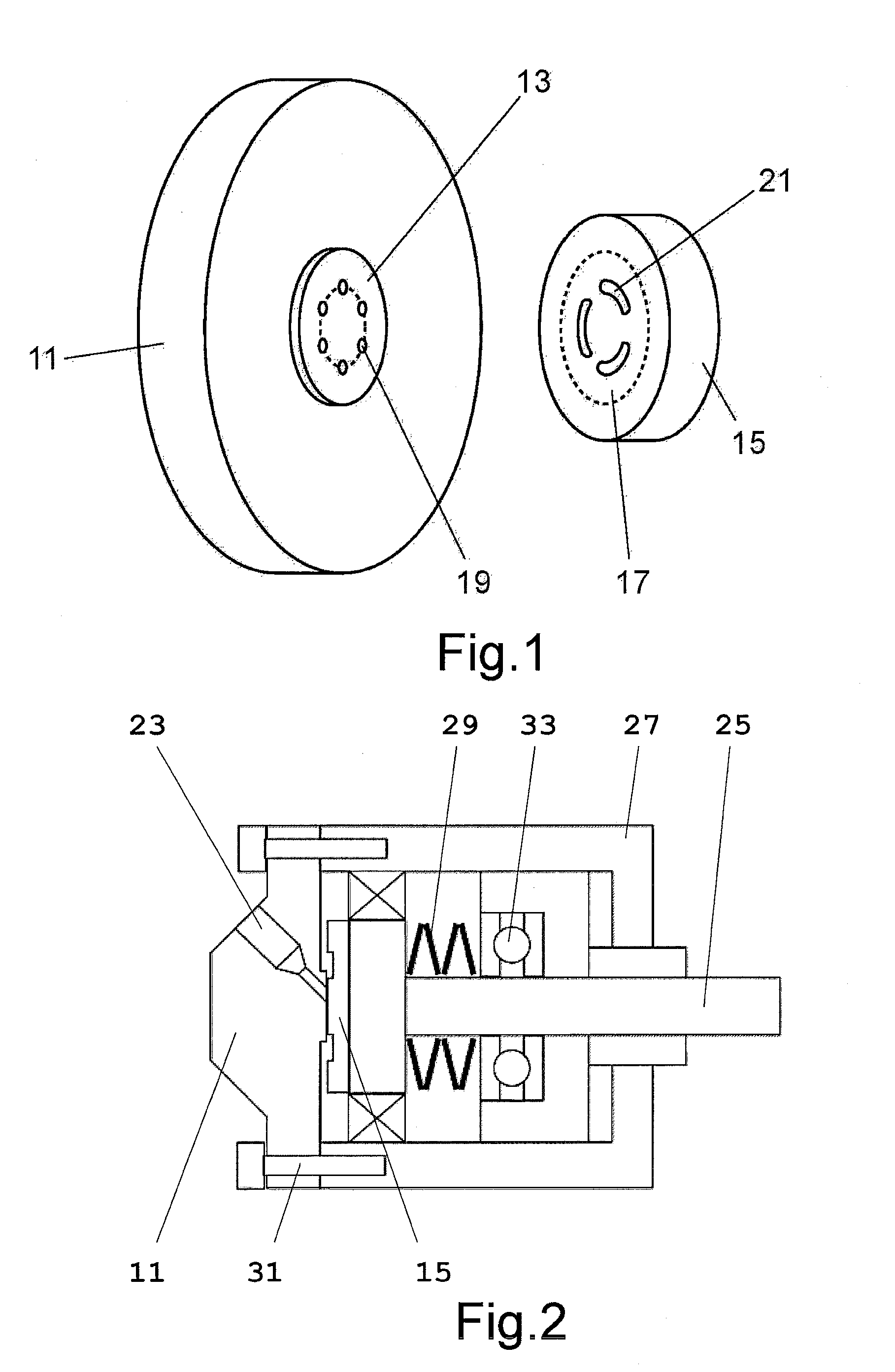
[0027]FIG. 1 is a schematic perspective view of a stator part and a rotor part of a flow channel switching valve according to an embodiment.

[0028]A stator 11 is made of stainless steel, and is integrally formed with a housing connected to flow channels. A stator sliding surface 13 of the stator 11 is connected to a rotor sliding surface 17 of a rotor 15, and through holes 19 disposed on the stator 11 are in communication with grooves 21 disposed on the rotor 15. The rotor 15 is made of, for example, a resin such as PEEK, and includes a plurality of arc-shaped grooves 21.

[0029]In order to improve the slidability, t...


PUM


Abstract

In order to improve the durability of a rotor, a flow channel switching valve is provided, which includes a stator having a contact plane and a rotor having a contact plane. The stator has circulation openings on the contact plane, and the circulation openings are respectively connected to a plurality of flow channels. The rotor has at least one groove for communicating two of the circulation openings of the stator. The rotor is forced to press against the contact plane of the stator to rotationally slide, so as to switch the circulation openings of the stator that need to be communicated. Polishing is performed on the contact plane of the stator after being applied with a diamond like carbons coating. Furthermore, the contact plane of the rotor is made of a resin.

Description

BACKGROUND OF THE INVENTION[0001]1. Field of the Invention[0002]The present invention generally relates to a flow channel switching valve for an analysis device such as a high performance liquid chromatograph.[0003]2. Description of Related Art[0004]In order to select a solution such as a sample or a solvent or introduce a sample into an analysis system from the exterior, an analysis device has a flow channel switching mechanism. For example, a high performance liquid chromatograph has a mechanism for switching mobile-phase flow channels for liquid transportation under a high pressure (several ten MPa) to introduce a sample solution under the atmospheric pressure into the flow channels, and the mechanism has a flow channel switching valve.[0005]In the prior art, the following flow channel switching valve (for example, Patent Document 1) is used for the above purpose, in which a disc-like rotor formed with switching grooves is capable of rotating while contacting a disc-like stator p...

Claims


Application Information

Patent Timeline
Patent Type & Authority Applications(United States)
IPC IPC(8): F16K31/02
CPCF16K11/0743G01N2030/202F16K25/005
Inventor YASUNAGA, KENICHI
Owner SHIMADZU CORP
Why Eureka
Try Eureka