

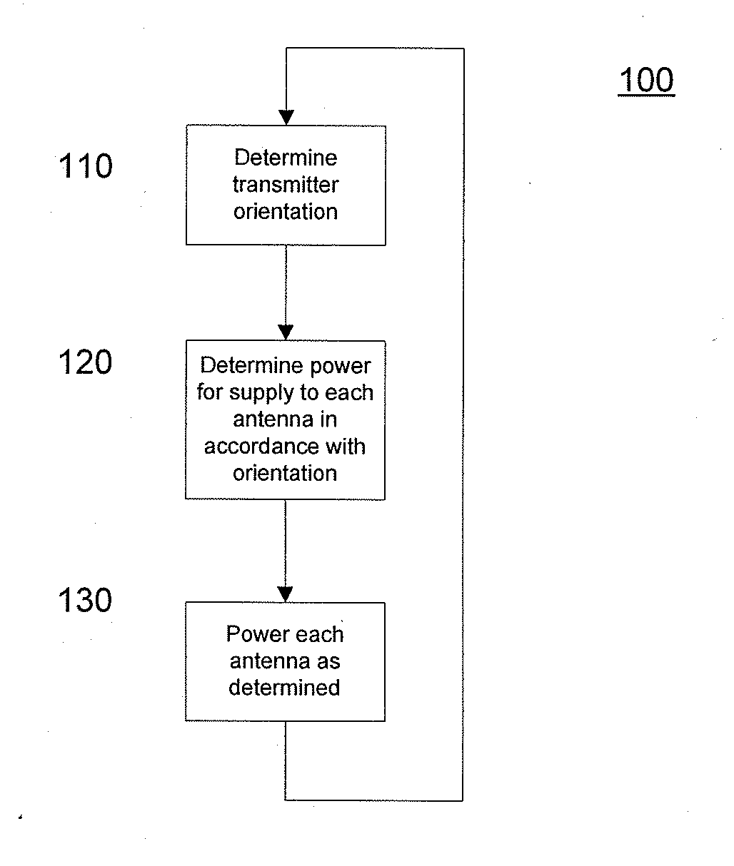
Method and apparatus for controlling radiation characteristics of transmitter of wireless device in correspondence with transmitter orientation
a wireless device and radiation characteristic technology, applied in the direction of resonant antennas, helical antennas, non-resonant long antennas, etc., can solve the problems of ineffective meeting, complex design considerations for wireless device transmitters and antennas, and increasing difficulty in designing wireless devices with sufficient transmitter performance and sufficiently low sar
- Summary
- Abstract
- Description
- Claims
- Application Information
AI Technical Summary
Benefits of technology
Problems solved by technology
Method used
Image

Examples
example 1
[0068]FIG. 4 illustrates a block diagram of a wireless device 300 showing components and interactions according to embodiments of the invention. The wireless device comprises an antenna 310, a branching circuit 320 for separating incoming signals 321 from outgoing signals 323 that have been received or are to be transmitted via the antenna 310, an incoming signal amplifier 330, an outgoing signal amplifier 340, a radio baseband controller 350, an orientation sensor 360 and a user notification element 370 for indicating a predetermined user notification such as an alarm indicating predetermined SAR levels, for example. The antenna 310 is used to receive as well as transmit electromagnetic signals in a wireless manner over the air using electromagnetic radiation which may lead to user irradiation which may be quantified in terms of SAR as described above.
[0069]The antenna 310 is operatively connected 311 to the branching circuit 320. The branching circuit 320 includes antenna drive ci...
example 2
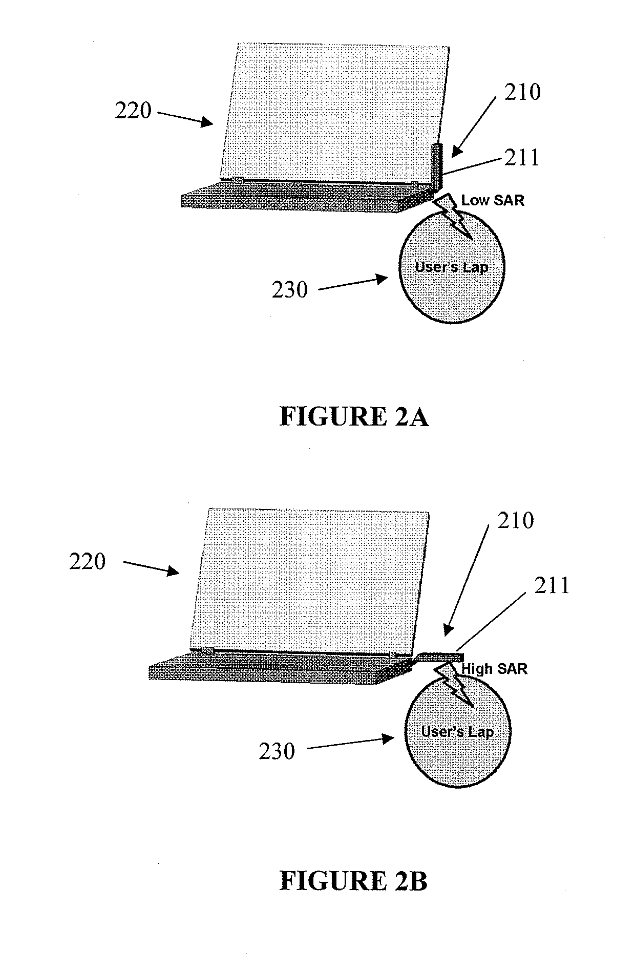
[0077]FIG. 6 illustrates a block diagram of a wireless device 500 according to another embodiment of the present invention. The wireless device comprises a radio baseband controller 550, an orientation sensor 560. The wireless device further comprises a switching device 521, which is configured to operatively activate the first antenna 511 and the second antenna 512. The radio baseband controller 550 can selectively operate the switching device 521 to select one of or both of the antennas 511 and 512 for operation such that electromagnetic radiation which may lead to user irradiation can be controlled such that a predetermined SAR level may be satisfied.
[0078]The first and second antennas 511 and 512 can be configured to have different radiation patterns, power levels orientations, wherein the radio baseband controller 550, based on the known characteristics of the antennas, and relative positioning of the one or more antennas provided by the orientation sensor 560, is configured to...
example 3
[0080]FIG. 7 illustrates a block diagram of a wireless device 600 according to another embodiment of the present invention. The wireless device comprises a first antenna drive circuit 601 and a second antenna drive circuit 602. Each antenna drive circuit includes respective branching circuits 621 and 622, incoming signal amplifiers 631 and 632 and outgoing signal amplifiers 641 and 642. The wireless device further comprises a radio baseband controller 650, an orientation sensor 660 and a user notification element 670. The wireless device may be configured to use the user notification element 670 for indicating a predetermined user notification, for example, an indication of predetermined communication quality or radiation exposure levels, for example. The antennas 611 and 612 may be used to receive as well as to transmit electromagnetic signals in a wireless manner over the air using electromagnetic radiation which may lead to user irradiation which may be quantified in terms of SAR...
PUM
 Abstract
Description
Claims
Application Information