Ultrasonic diagnostic apparatus

a diagnostic apparatus and ultrasonic technology, applied in tomography, instruments, applications, etc., can solve the problems of poor spatial resolution, inability to express color modes, etc., and achieve the effect of improving frame rate and reducing image generation tim

Inactive Publication Date: 2010-11-04
FUJIFILM CORP
View PDF3 Cites 32 Cited by
  • Summary
  • Abstract
  • Description
  • Claims
  • Application Information

AI Technical Summary

Benefits of technology

[0012]According to the one aspect of the present invention, by transmitting and receiving the pulse trains, each including plural pulses respectively having frequency components of orthogonal frequency division multiplexing waves, in the same direction, ...

Problems solved by technology

Further, in order to secure the sensitivity in detection of the Doppler effect, plural times (four to ten times) of transmissions are perf...

Method used


Image

  • Ultrasonic diagnostic apparatus
  • Ultrasonic diagnostic apparatus
  • Ultrasonic diagnostic apparatus

Examples


first embodiment

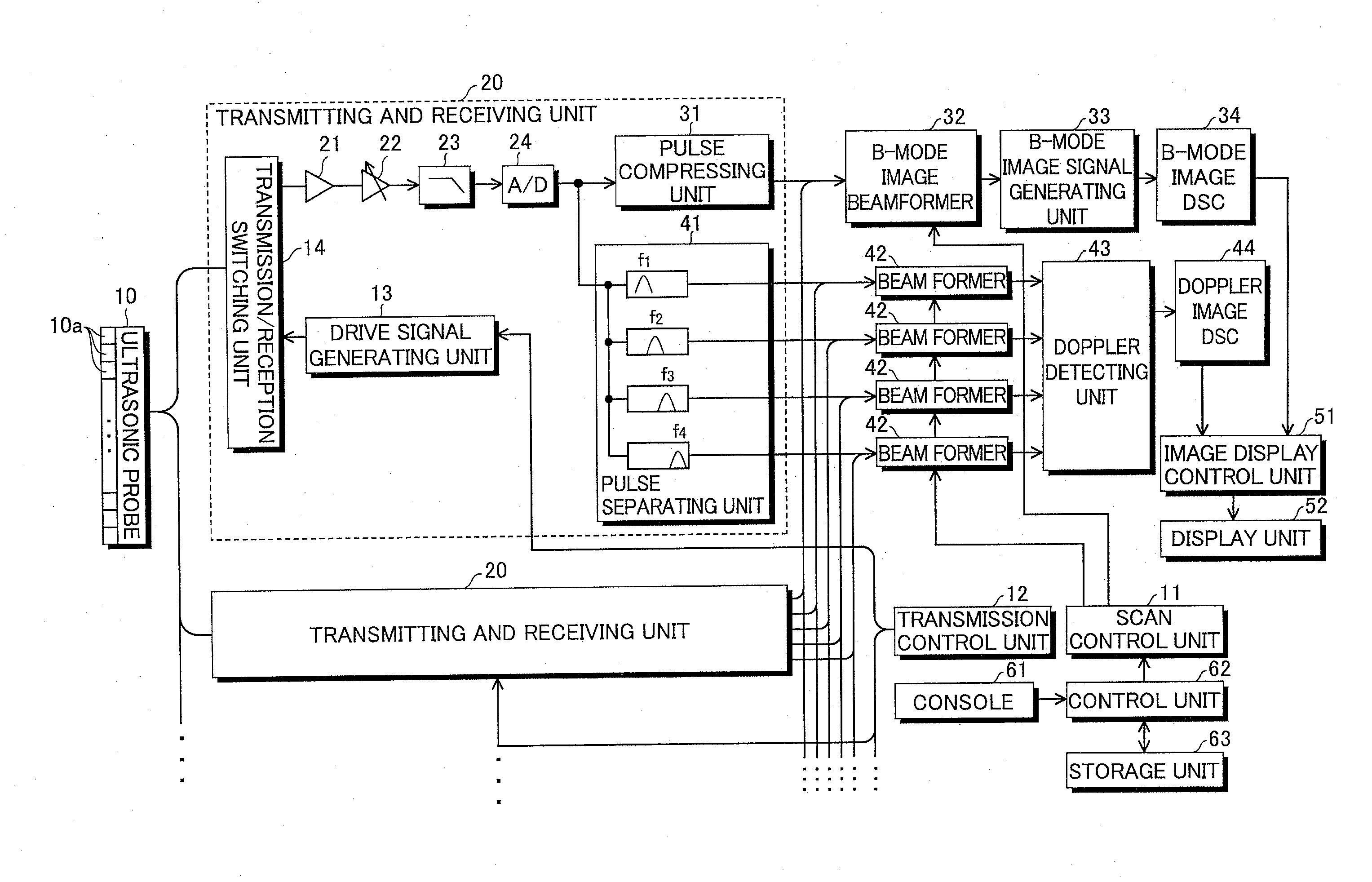
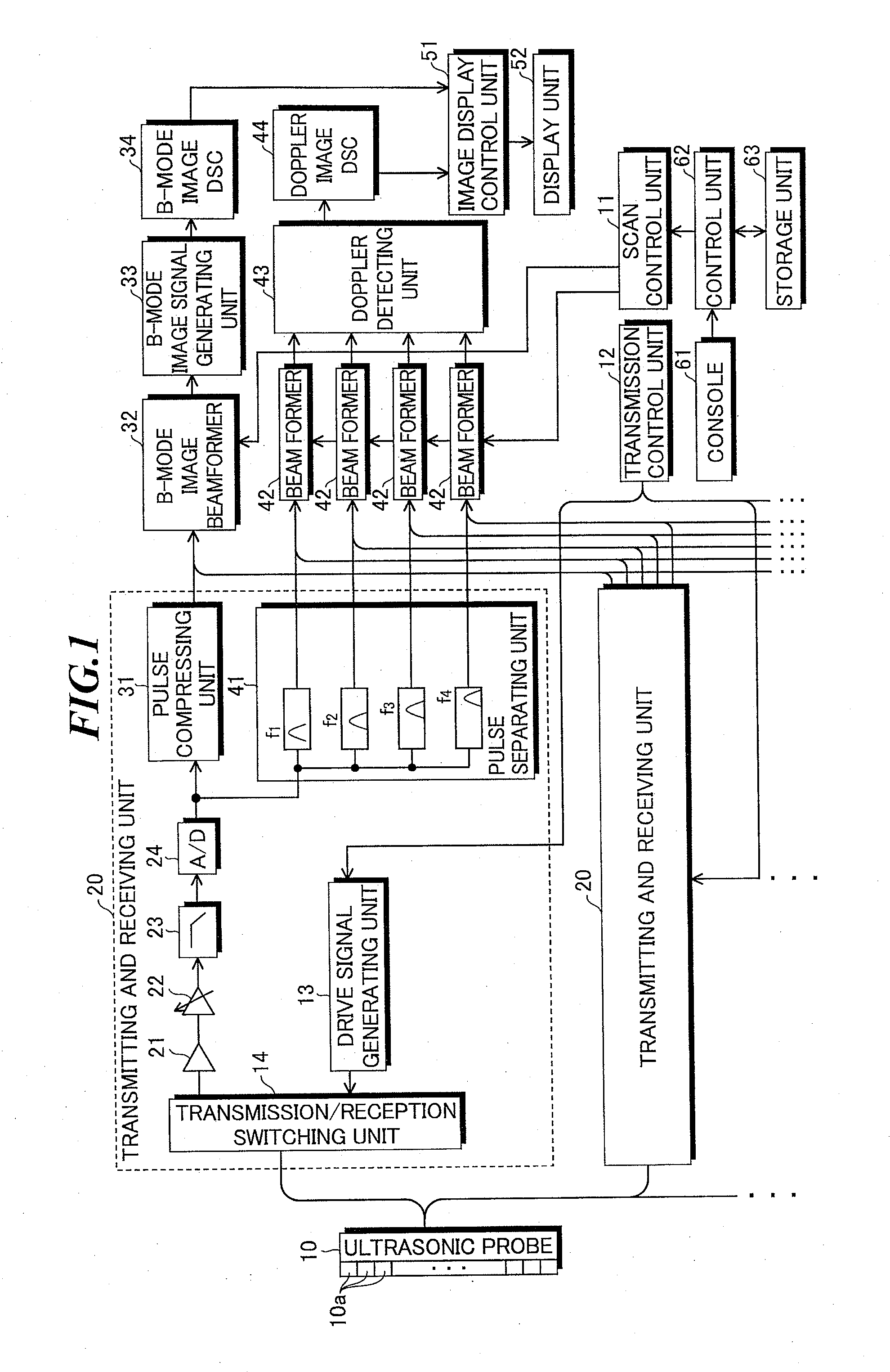
[0026]FIG. 1 is a block diagram showing a configuration of an ultrasonic diagnostic apparatus according to the present invention. The ultrasonic diagnostic apparatus has an ultrasonic probe 10 including plural ultrasonic transducers 10a, a scan control unit 11, a transmission control unit 12, transmitting and receiving units 20 having plural channels corresponding to the plural ultrasonic transducers 10a, a B-mode image beamformer 32, a B-mode image signal generating unit 33, a B-mode image DSC 34, Doppler image beam formers 42, a Doppler detecting unit 43, a Doppler image DSC 44, an image display control unit 51, a display unit 52, a console 61, a control unit 62, and a storage unit 63.

[0027]The plural ultrasonic transducers 10a of the ultrasonic probe 10 transmit ultrasonic waves to an object to be inspected according to applied drive signals, and receive ultrasonic echoes propagating from the object to output reception signals. These ultrasonic transducers 10a are one-dimensional...

second embodiment

[0062]Next, the present invention will be explained.

[0063]FIG. 12 is a block diagram showing a configuration of an ultrasonic diagnostic apparatus according to the second embodiment of the present invention. In the second embodiment, in place of the transmitting and receiving units 20 and the Doppler detecting unit 43, transmitting and receiving units 20a and a Doppler detecting unit 43a are used. The rest of the configuration is the same as that in the first embodiment.

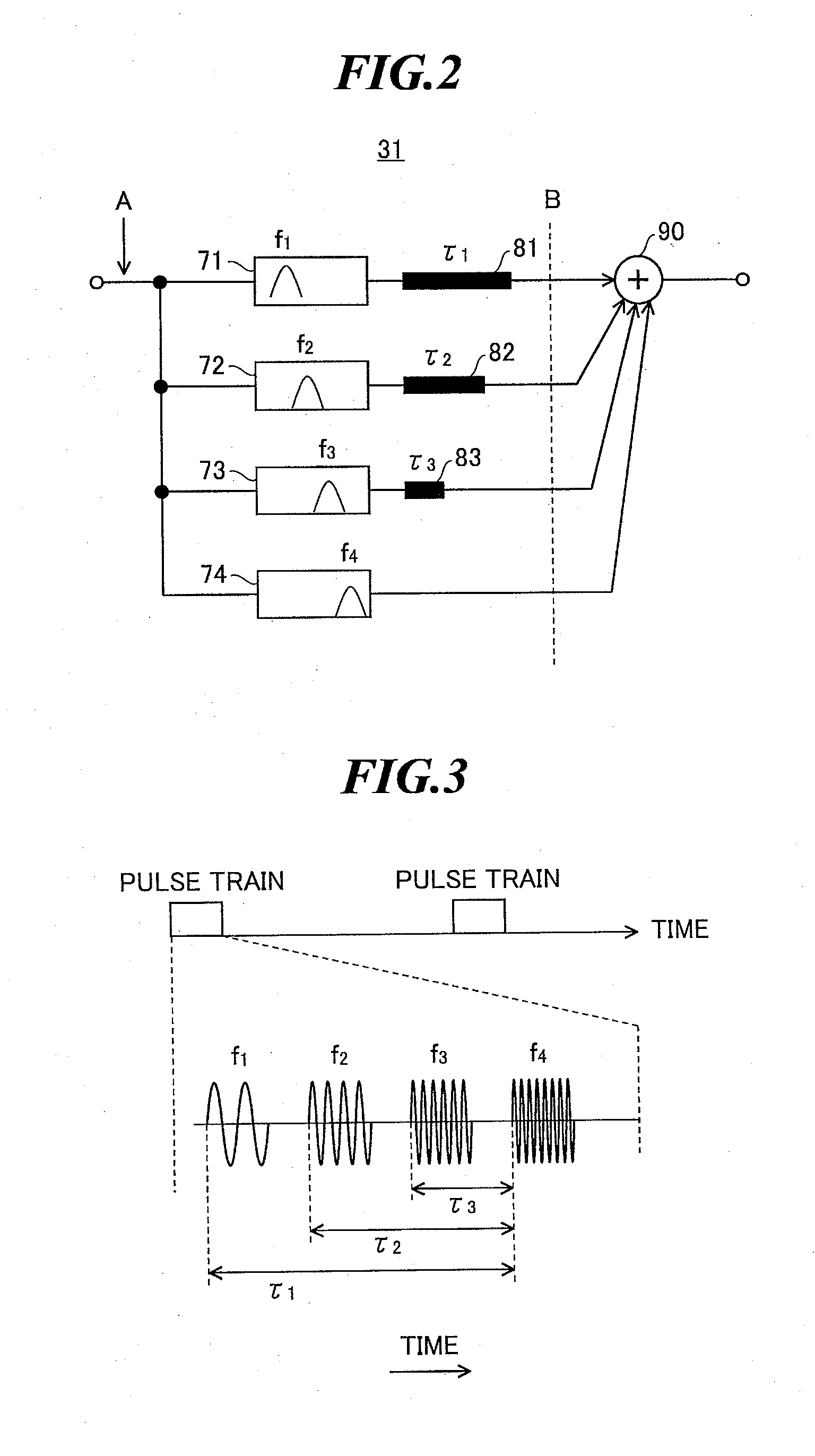
[0064]In the transmitting and receiving unit 20a, a pulse separating unit 41a includes four bandpass filters having center pass frequencies of f1-f4, respectively, and additionally includes three delay elements respectively providing delay times of τ1-τ3. These may also serve as the bandpass filters 71-74 and the delay elements 81-83 of the pulse compressing unit as shown in FIG. 2. Accordingly, in the second embodiment, a pulse compressing unit 31a includes only an adder. Further, in the Doppler detecting unit 43a, ...


PUM


Abstract

An ultrasonic diagnostic apparatus in which an image generation time can be reduced and a frame rate can be improved even in a color mode in which a two-dimensional color Doppler image obtained due to Doppler effect is combined with a B-mode image. The ultrasonic diagnostic apparatus includes an ultrasonic probe, a transmission system signal processing unit for supplying drive signals to the ultrasonic probe to transmit pulse trains, each including plural pulses respectively having frequency components of orthogonal frequency division multiplexing waves orthogonal to one another and having different center frequencies from one another, in the same direction, and a reception system signal processing unit for pulse-compressing the plural pulses having different frequency components included in each reception signal outputted from the ultrasonic probe which has received the pulse trains from the same direction, and generating a B-mode image signal based on the compressed pulse.

Description

CROSS-REFERENCE TO RELATED APPLICATION[0001]The present application claims priority from Japanese Patent Application No. 2008-225415 filed on Sep. 3, 2008, the contents of which are incorporated herein by reference in their entirety.BACKGROUND OF THE INVENTION[0002]1. Field of the Invention[0003]The present invention relates to an ultrasonic diagnostic apparatus for imaging organs within a living body by transmitting and receiving ultrasonic waves to generate ultrasonic images to be used for diagnoses.[0004]2. Description of a Related Art[0005]In an ultrasonic diagnostic apparatus for medical use, typically, an ultrasonic probe including plural ultrasonic transducers having functions of transmitting and receiving ultrasonic waves is used. An object to be inspected is scanned with an ultrasonic beam transmitted from the plural ultrasonic transducers, ultrasonic echoes reflected within the object are received by the plural ultrasonic transducers, and thereby, image information (B-mode...

Claims


Application Information

Patent Timeline
IPC IPC(8): A61B8/14
CPCA61B8/14A61B8/488G01S15/8979G01S15/8959G01S15/8961G01S15/8952
Inventor SATOH, TOMOO
Owner FUJIFILM CORP
Why Eureka
Try Eureka