Linear roller bearing assembly and sub-assembly and reciprocating machinery incorporating the same

a technology of roller bearings and components, which is applied in the direction of bearing units, rigid supports of bearings, machines/engines, etc., can solve the problems of reducing the life and performance of machines, reducing performance and efficiency, and commonly used spiral flexure bearings, so as to increase the carnot efficiency of a stirling engine power module and high thermodynamic engine efficiency and power density.

Active Publication Date: 2010-11-11
STIRLING INNOVATIONS LLC
View PDF16 Cites 9 Cited by
  • Summary
  • Abstract
  • Description
  • Claims
  • Application Information

AI Technical Summary

Benefits of technology

[0015]According to other embodiments, multi-cylinder Stirling engines having Stirling engine power modules connected together in series to form a closed loop are disclosed. These multi-cylinder Stirling engines can

Problems solved by technology

Rubbing of the piston would reduce the machine's life and performance due to wear, and contamination of both the working gas and the internal heat exchangers.
The bearings should not require lubrication that would contaminate the working gas and thus reduce performance and efficiency.
Commonly used spiral flexure bearings (see e.g. FIG. 6 of U.S. Pat. No. 5,647,217) are limited in their stroke capability, frequency of operation, and radial load capacity.
They can be expensive to manufacture, due to the extremely close dimensional tolerances required.
Simple gas bearings do not provide rotational restraint that is usually required by linear alternators or motors.
One problem with the linear bearing shown in FIGS. 14 and 15 of the '045 patent is that, over time, the straps can loosen around the rollers.
The rollers can therefore slide laterally or slip rotationally within the straps to degrade the per

Method used


Image

  • Linear roller bearing assembly and sub-assembly and reciprocating machinery incorporating the same
  • Linear roller bearing assembly and sub-assembly and reciprocating machinery incorporating the same
  • Linear roller bearing assembly and sub-assembly and reciprocating machinery incorporating the same

Examples


first embodiment

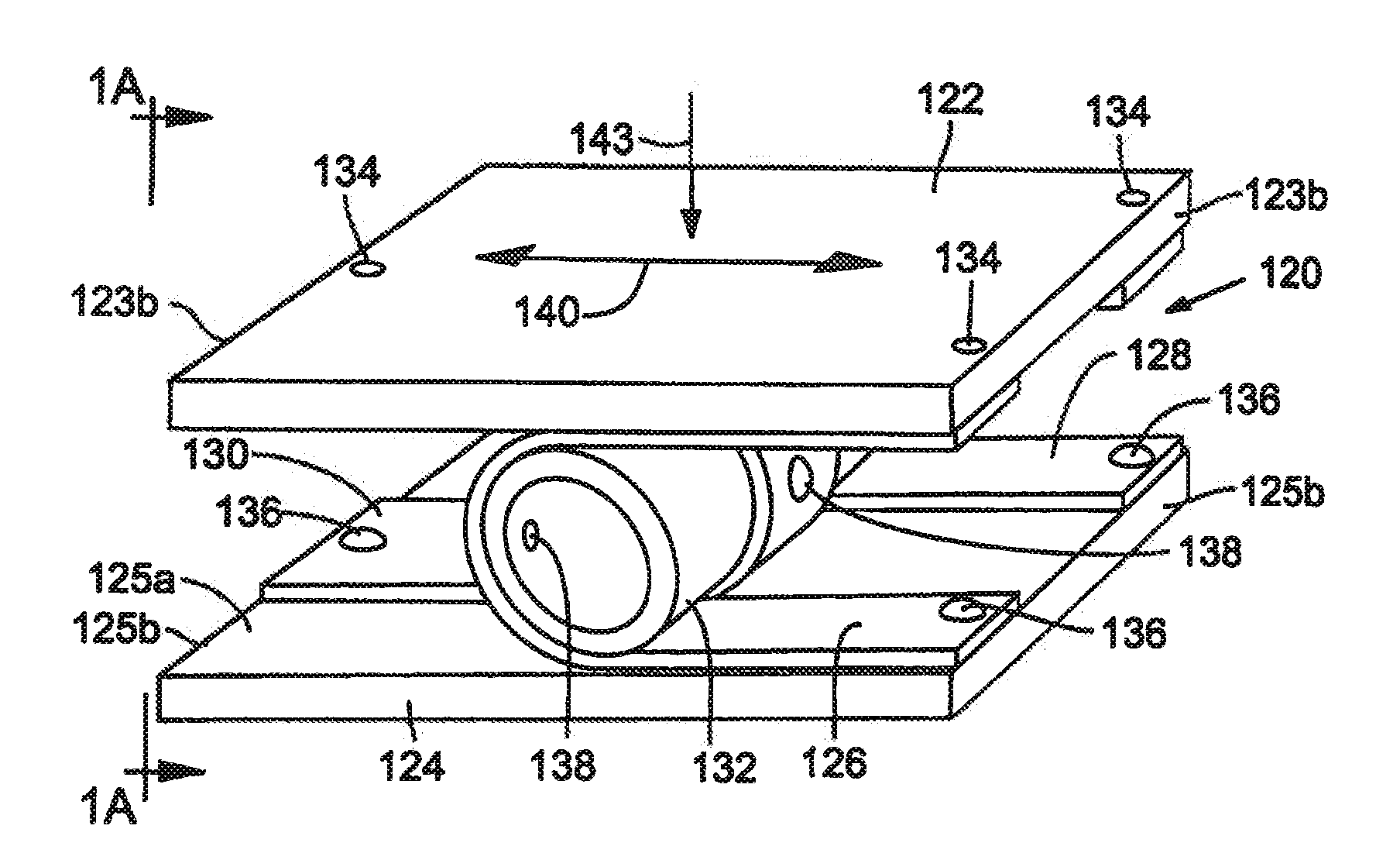
[0056]FIG. 1 is a perspective view of a roller bearing sub-assembly according to the invention. FIG. 1A is an end view of the roller bearing sub-assembly shown in FIG. 1, taken along line 1A-1A of FIG. 1.

[0057]Referring to FIGS. 1 and 1A, a roller bearing sub-assembly 120 includes mounting portions or rails (e.g., first mounting portion 122 and second mounting portion 124), straps (e.g., first peripheral strap 126, second peripheral strap 128 and central strap 130), a roller (e.g., roller 132), and attachments (e.g., first mounting portion attachments 134, second mounting portion attachments 136 and roller attachments 138).

[0058]The first mounting portion 122 includes a strap-supporting surface 123a and side surfaces 123b on opposite edges of the strap-supporting surface 123a. Likewise, the second mounting portion 124 includes a strap-supporting surface 125a and side surfaces 125b on opposite edges of the strap-supporting surface 125a. The strap-supporting surfaces 123a and 125a con...

second embodiment

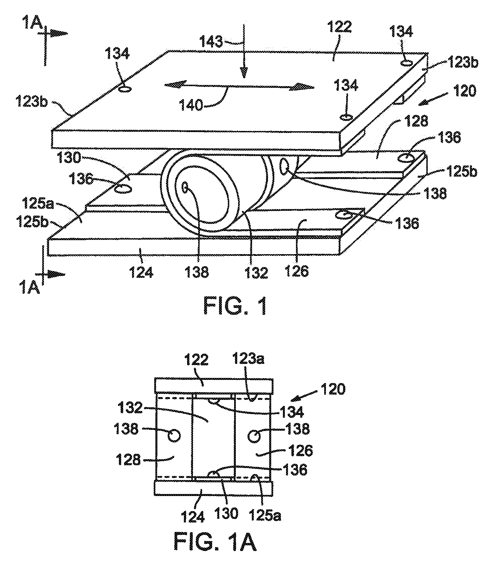
[0072]FIG. 2 is a perspective view of a roller bearing sub-assembly according to the invention.

[0073]Referring to FIG. 2, a roller bearing sub-assembly 220 according to a second embodiment includes mounting portions or rails (e.g., first mounting portion 222 and second mounting portion 224), straps (e.g., first peripheral straps 126a and 126b, second peripheral straps 128a and 128b and central straps 130a and 130b), rollers (e.g., rollers 132a and 132b), and attachments (e.g., first mounting portion attachments 134a and 134b, second mounting portion attachments 136a and 136b and roller attachments 138a and 138b).

[0074]The mounting portions, straps, and attachments may all be provided as exemplarily described with respect to the roller bearing sub-assembly 120 according to the first embodiment. However, in the roller bearing sub-assembly 220, each of the first peripheral straps 126a and 126b, second peripheral straps 128a and 128b and central straps 130a and 130b, are secured to the ...

third embodiment

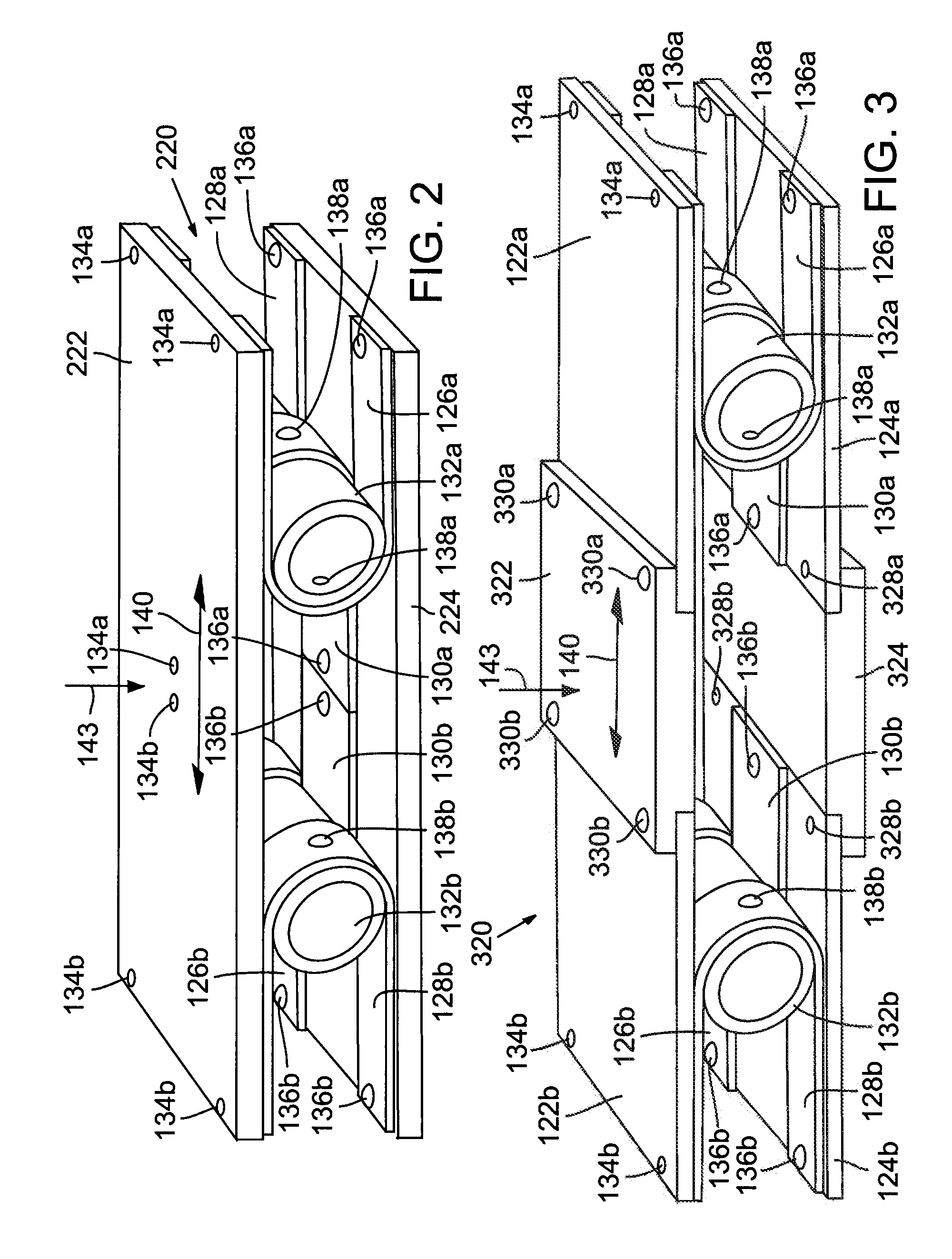
[0078]FIG. 3 is a perspective view of a roller bearing sub-assembly according to the invention.

[0079]Referring to FIG. 3, a roller bearing sub-assembly 320 according to a third embodiment includes mounting portions or rails (e.g., first mounting portions 122a and 122b and second mounting portions 124a and 124b), straps (e.g., first peripheral straps 126a and 126b, second peripheral straps 128a and 128b and central straps 130a and 130b), rollers (e.g., rollers 132a and 132b), attachments (e.g., first mounting portion attachments 134a and 134b, second mounting portion attachments 136a and 136b, roller attachments 138a and 138b, first spacer attachments 330a and 330b and second spacer attachments 328a and 328b) and mounting portion spacers or rail spacers (e.g., first mounting portion spacer 322 and second mounting portion spacer 324). The first spacer attachments 330a and 330b and second spacer attachments 328a and 328b may be provided as attachments such as those exemplarily describe...


PUM

PropertyMeasurementUnit
Angleaaaaaaaaaa
Angleaaaaaaaaaa
Temperatureaaaaaaaaaa

Abstract

Linear roller bearing assemblies can include a hub, a collar around the hub and roller bearing sub-assemblies disposed in a radial pattern around the hub. The roller bearing sub-assemblies can guide linear movement of the hub relative to the collar along a selected direction. Each roller bearing sub-assembly can include a roller and straps wrapped partially around the roller. Each strap is connected to at least one of the hub and the collar. And at least one of the straps can be connected to the roller while at least one of the straps can be circumferentially free of the roller. The hub and collar are moveable relative to each other along the selected direction for a distance that is approximately half of a circumference of the roller. Methods of forming linear roller bearing assemblies are also disclosed, as are multi-cylinder Stirling engines and a thermal energy recovery system.

Description

[0001]CROSS-REFERENCE TO RELATED PATENT APPLICATION[0002]This application claims the benefit of U.S. Provisional App. No. 61 / 176,221, filed on May 7, 2009, the disclosure of which is incorporated herein by reference in its entirety.BACKGROUND[0003]1. Technical Field[0004]This disclosure relates to linear roller bearing assemblies, roller-bearing sub-assemblies, and reciprocating machinery incorporating the same, more particularly in Stirling engines and cryocoolers.[0005]2. Description of the Related Art[0006]Free-piston Stirling engines and cryocoolers include linear bearings to guide and support components such as pistons which reciprocate within a pressurized gas environment. Differential gas pressures across the piston are sealed by a narrow, non-contact annular gap (clearance seal). It is desirable to maintain concentricity of this gap to maximize performance and efficiency by minimizing energy losses due to gas leakage through said gap. These bearings should prevent contact be...

Claims


Application Information

Patent Timeline
IPC IPC(8): F02G1/04F16C13/02B21D53/10
CPCF16C11/12F16H19/06Y10T29/49682Y10T29/49686Y10T29/49641Y10T29/4968F16C29/00F16C29/04
Inventor EMIGH, S. GRANT
Owner STIRLING INNOVATIONS LLC
Why Eureka
Try Eureka