Air Supply for Components of a Split-Cycle Engine

a split-cycle engine and air supply technology, applied in the direction of liquid fuel engines, combustion-air/fuel-air treatment, non-mechanical valves, etc., can solve the problems of compressed air leakage, limited flexibility, and efficient and fast cam-driven actuation mechanisms

Inactive Publication Date: 2010-11-11
SKADERI GRUP LLC
View PDF79 Cites 34 Cited by
  • Summary
  • Abstract
  • Description
  • Claims
  • Application Information

AI Technical Summary

Problems solved by technology

A cam driven actuation mechanism is efficient and fast, but has limited flexibility.
These components g

Method used


Image

  • Air Supply for Components of a Split-Cycle Engine
  • Air Supply for Components of a Split-Cycle Engine
  • Air Supply for Components of a Split-Cycle Engine

Examples


first embodiment

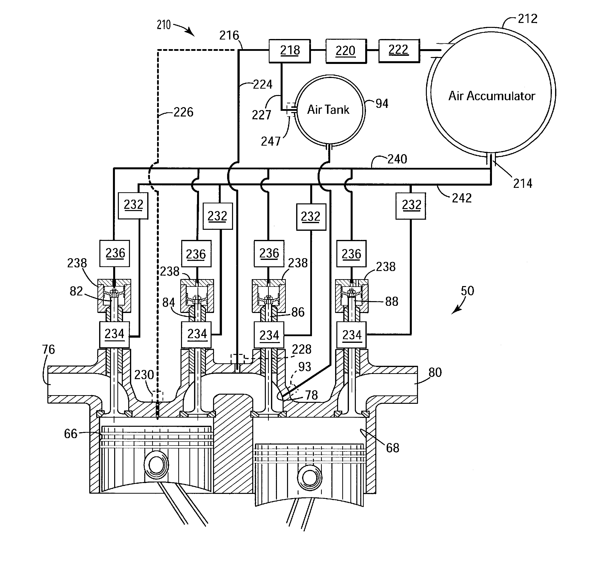
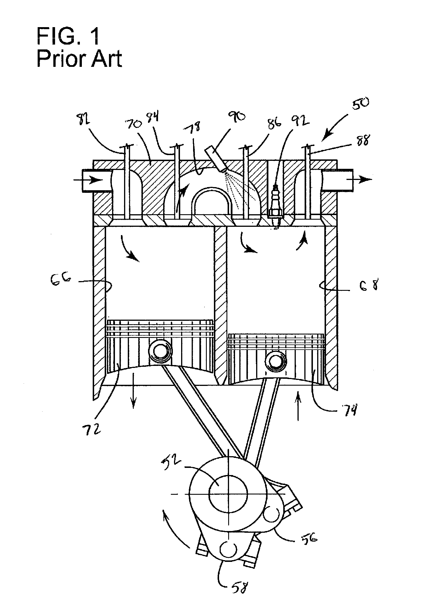
[0032]Referring now to the first embodiment of FIG. 3 in detail, numeral 50 generally indicates a diagrammatic representation of a split-cycle engine of the type shown in FIG. 1. According to the present invention, compressed air generated by the split-cycle engine 50 is supplied to air actuators 234 for actuating the valves 82, 84, 86, 88 and to air springs 238 for supporting the valves 82, 84, 86, 88.

[0033]Compression cylinder 66 draws in intake air during the intake stroke of the engine 50. The compression piston 72 pressurizes the air charge and drives the air charge into the one or more crossover passages 78. One or more check valves 228 in the one or more crossover passages 78 (preferably one check valve 228 in each crossover passage 78) control flow of compressed air into an air processing system 210 through one or more air input lines 224. The air input lines 224 can preferably connect directly from the crossover passage(s) 78 to the air processing system 210. Though check v...

second embodiment

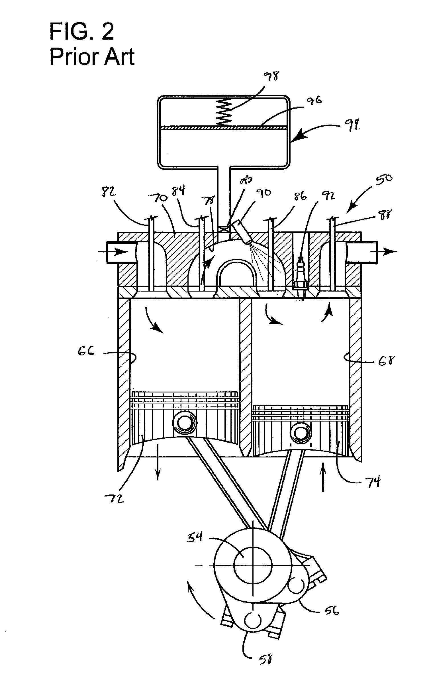
[0038]FIG. 4 shows a second air-hybrid embodiment of the present invention. In this second embodiment, the split-cycle engine 50 is a split-cycle air hybrid engine. That is, the split-cycle engine further includes an air tank 94 (shown schematically) similar to the air tank detailed in FIG. 2. Compressed air from the one or more crossover passages 78 is fed into the air tank 94 through valve 93, which can be a solenoid valve or any other appropriate type of valve. The air tank 94 is thereby used to store energy in the form of compressed air. At an appropriate time, the compressed air stored in the air tank 94 can be fed back into the one or more crossover passages 78 in order to power the crankshaft 54. Further implementation details of operations modes of the air hybrid configuration are provided in the Air-Hybrid patent.

[0039]An air input line 227 connects the air tank 94 to the air processing system 210 (of the type described in reference to the first embodiment) via a check valv...


PUM


Abstract

The present invention generally relates to providing an air supply for components associated with an engine. More particularly, the present invention relates to a system and method for using compressed air generated by a split-cycle engine to power components such as valves or air springs associated with the split-cycle engine.

Description

CROSS REFERENCE TO RELATED APPLICATIONS[0001]This application claims the benefit of U.S. Provisional Patent Application No. 61 / 176,263 filed May 7, 2009, the contents of which are incorporated by reference herein.TECHNICAL FIELD[0002]The present invention generally relates to providing an air supply for components associated with an engine. More particularly, the present invention relates to a system and method for using compressed air generated by a split-cycle engine to power components such as valves or air springs associated with the split-cycle engine.BACKGROUND OF THE INVENTION[0003]For purposes of clarity, the term “conventional engine” as used in the present application refers to an internal combustion engine wherein all four strokes of the well known Otto or Diesel cycles (the intake, compression, expansion and exhaust strokes) are contained in each piston / cylinder combination of the engine. Each stroke requires one half revolution of the crankshaft (180 degrees crank angle...

Claims


Application Information

Patent Timeline
IPC IPC(8): F02B33/22F02M35/02F16K31/12
CPCF01L9/026F01L2001/34446F02B21/00F02B33/22F02B33/30F02B33/44F02D17/026F02B2700/035F02B2720/135F02B2720/235F02D17/023F02B75/021F02B33/446F01L9/16
Inventor GILBERT, IAN P.PERKINS, ANTHONY S.PIRAULT, JEAN-PIERREMELDOLESI, RICCARDO
Owner SKADERI GRUP LLC
Why Eureka
Try Eureka