Isotope production system and cyclotron

a production system and isotope technology, applied in the field of cyclotrons, can solve the problems of other undesirable reactions, irretrievable loss of particles, and undesirable qualities or properties of conventional vacuum systems

Active Publication Date: 2010-11-11
GENERAL ELECTRIC CO
View PDF38 Cites 44 Cited by
  • Summary
  • Abstract
  • Description
  • Claims
  • Application Information

AI Technical Summary

Problems solved by technology

The neutral particle is irretrievably lost and may also cause other undesirable reactions within the acceleration chamber.
However, conventional vacuum systems may have undesirable qualities or properties.
For example, conventional vacuum systems can be large and require extensive space.
This may be problematic, especially when the cyclotron and vacuum system must be used in a hospital room that was not originally designed for using large systems.
Furthermore, with several interconnected components there may be more interfaces or regions where leaks may occur due to damaged or worn-out parts.
This may lead to costly and time-consuming maintenance of the vacuum system.
However, the oil within the diffusion pumps may backstream into the acceleration chamber of the cyclotron.
This may reduce the vacuum system's ability to remove the gas particles, which, in turn, may negatively affect the efficiency of the cyclotron.
Furthermore, oil within the acceleration chamber may induce electrical discharges that damage the electrical components used by the cyclotron to create the electrical field.

Method used


Image

  • Isotope production system and cyclotron
  • Isotope production system and cyclotron
  • Isotope production system and cyclotron

Examples


Embodiment Construction

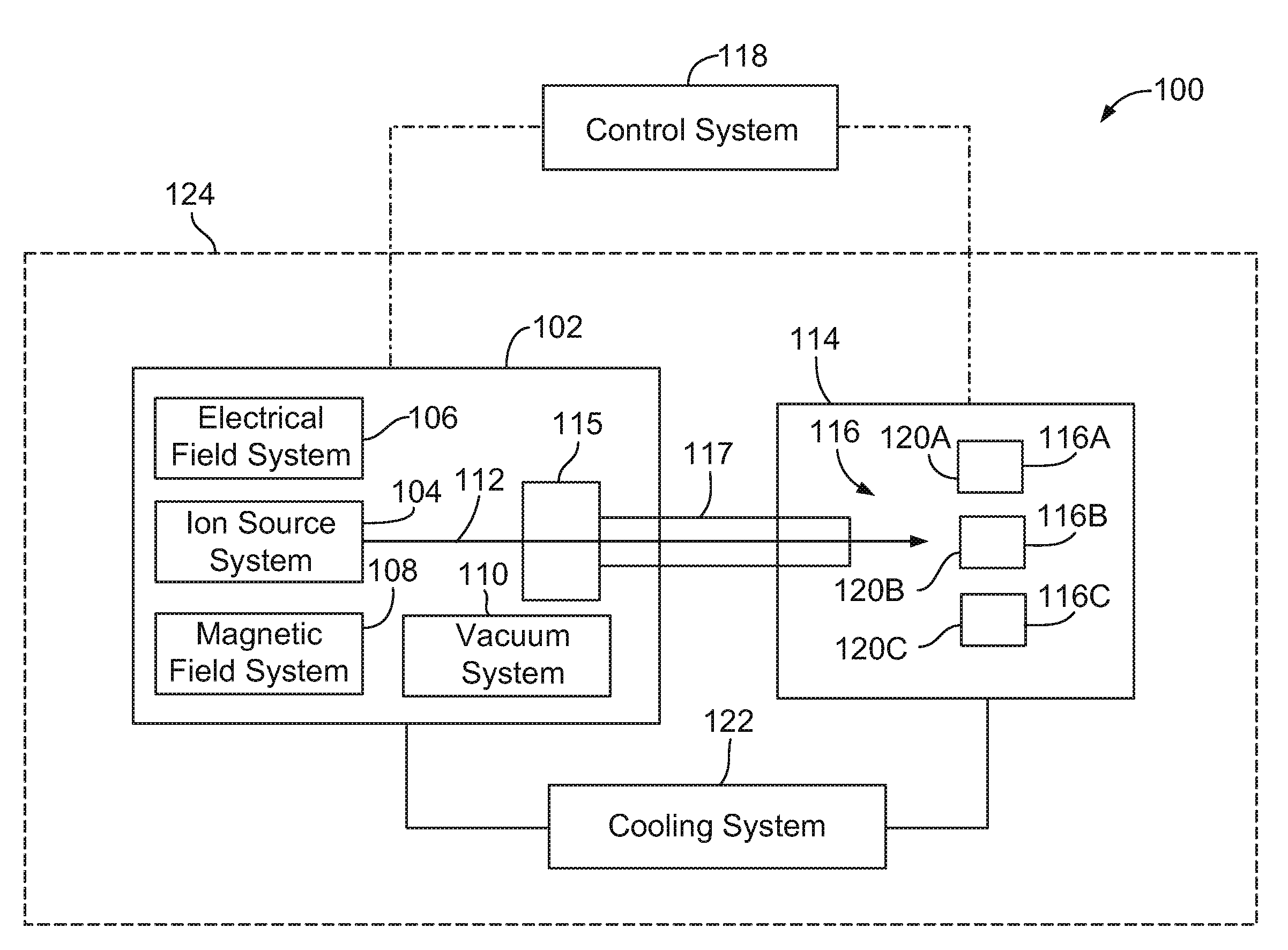
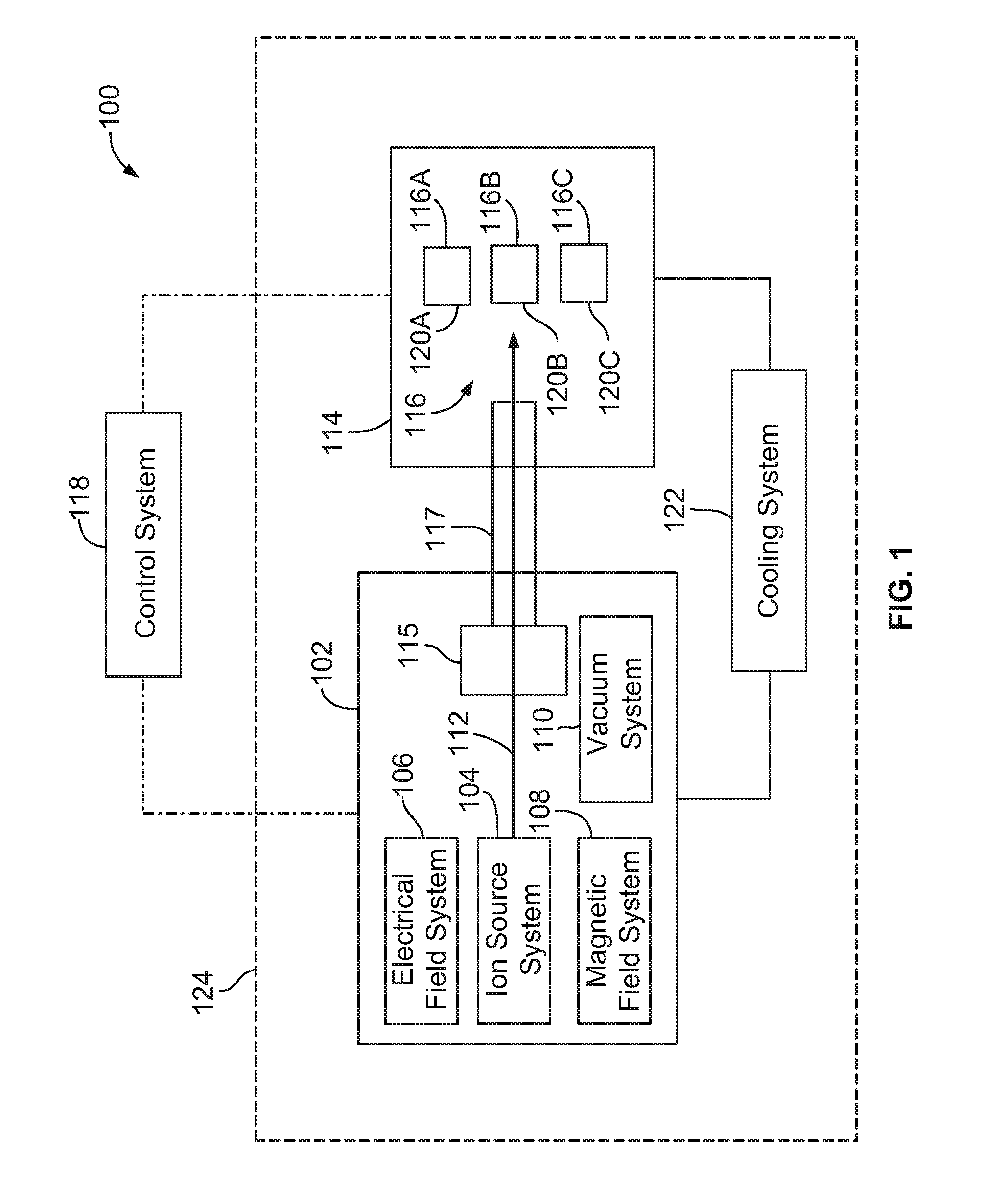
[0021]FIG. 1 is a block diagram of an isotope production system 100 formed in accordance with one embodiment. The system 100 includes a cyclotron 102 that has several sub-systems including an ion source system 104, an electrical field system 106, a magnetic field system 108, and a vacuum system 110. During use of the cyclotron 102, charged particles are placed within or injected into the cyclotron 102 through the ion source system 104. The magnetic field system 108 and electrical field system 106 generate respective fields that cooperate with one another in producing a particle beam 112 of the charged particles. The charged particles are accelerated and guided within the cyclotron 102 along a predetermined path. The system 100 also has an extraction system 115 and a target system 114 that includes a target material 116.

[0022]To generate isotopes, the particle beam 112 is directed by the cyclotron 102 through the extraction system 115 along a beam transport path 117 and into the targ...


PUM


Abstract

A cyclotron that includes a magnet yoke having a yoke body that surrounds an acceleration chamber. The cyclotron also includes a magnet assembly to produce magnetic fields to direct charged particles along a desired path. The magnet assembly is located in the acceleration chamber. The magnetic fields propagate through the acceleration chamber and within the magnet yoke, wherein a portion of the magnetic fields escapes outside of the magnet yoke as stray fields. The cyclotron also includes a vacuum pump that is coupled to the yoke body. The vacuum pump is configured to introduce a vacuum into the acceleration chamber. The magnet yoke is dimensioned such that the vacuum pump does not experience magnetic fields in excess of 75 Gauss.

Description

CROSS-REFERENCES TO RELATED APPLICATIONS[0001]The present application includes subject matter related to subject matter disclosed in patent applications having Attorney Docket No. 236099 (553-1442US) entitled “ISOTOPE PRODUCTION SYSTEM AND CYCLOTRON HAVING REDUCED MAGNETIC STRAY FIELDS,” and Attorney Docket No. 236098 (553-1441US) entitled “ISOTOPE PRODUCTION SYSTEM AND CYCLOTRON HAVING A MAGNET YOKE WITH A PUMP ACCEPTANCE CAVITY,” filed contemporaneously with the present application, both of which are incorporated by reference in their entirety.BACKGROUND OF THE INVENTION[0002]Embodiments of the invention relate generally to cyclotrons, and more particularly to cyclotrons used to produce radioisotopes.[0003]Radioisotopes (also called radionuclides) have several applications in medical therapy, imaging, and research, as well as other applications that are not medically related. Systems that produce radioisotopes typically include a particle accelerator, such as a cyclotron, that acc...

Claims


Application Information

Patent Timeline
Patent Type & Authority Applications(United States)
IPC IPC(8): H05H13/00H05H7/00
CPCH05H13/00H05H6/00
Inventor NORLING, JONASERIKSSON, TOMAS
Owner GENERAL ELECTRIC CO
Why Eureka
Try Eureka