Compensated directional resistivity measurements

Inactive Publication Date: 2010-11-11
SCHLUMBERGER TECH CORP
View PDF42 Cites 15 Cited by
  • Summary
  • Abstract
  • Description
  • Claims
  • Application Information

AI Technical Summary

Benefits of technology

[0009]Exemplary embodiments of the present invention may advantageously provide several technical advantages. For example, by computing a composite ratio the invention enables the transmitter moments, the receiver moments, as well as electronic errors (in both amplitude and phase) to be mathematically canceled out of the voltage (or magnetic field) measurements. By eliminating these error sources, the invention provides for directional resistivity measurements having improved accuracy. The result is a fully compensated directional resistivity measurement.
[0010]In certain advantageous embodiments of the invention, the azimuthal sensitivity of the computed composite ratio is approximately proportional

Problems solved by technology

While tilted antennae have been utilized commercially, one drawback with their use is that they transmit and/or receive mixed mode electromagnetic waves which do not allow small (e.g., transversal) signals to be easily separated out in the presence of measurement noises.
In order to make reliable measurements, the tran

Method used


Image

  • Compensated directional resistivity measurements
  • Compensated directional resistivity measurements
  • Compensated directional resistivity measurements

Examples


embodiment 100

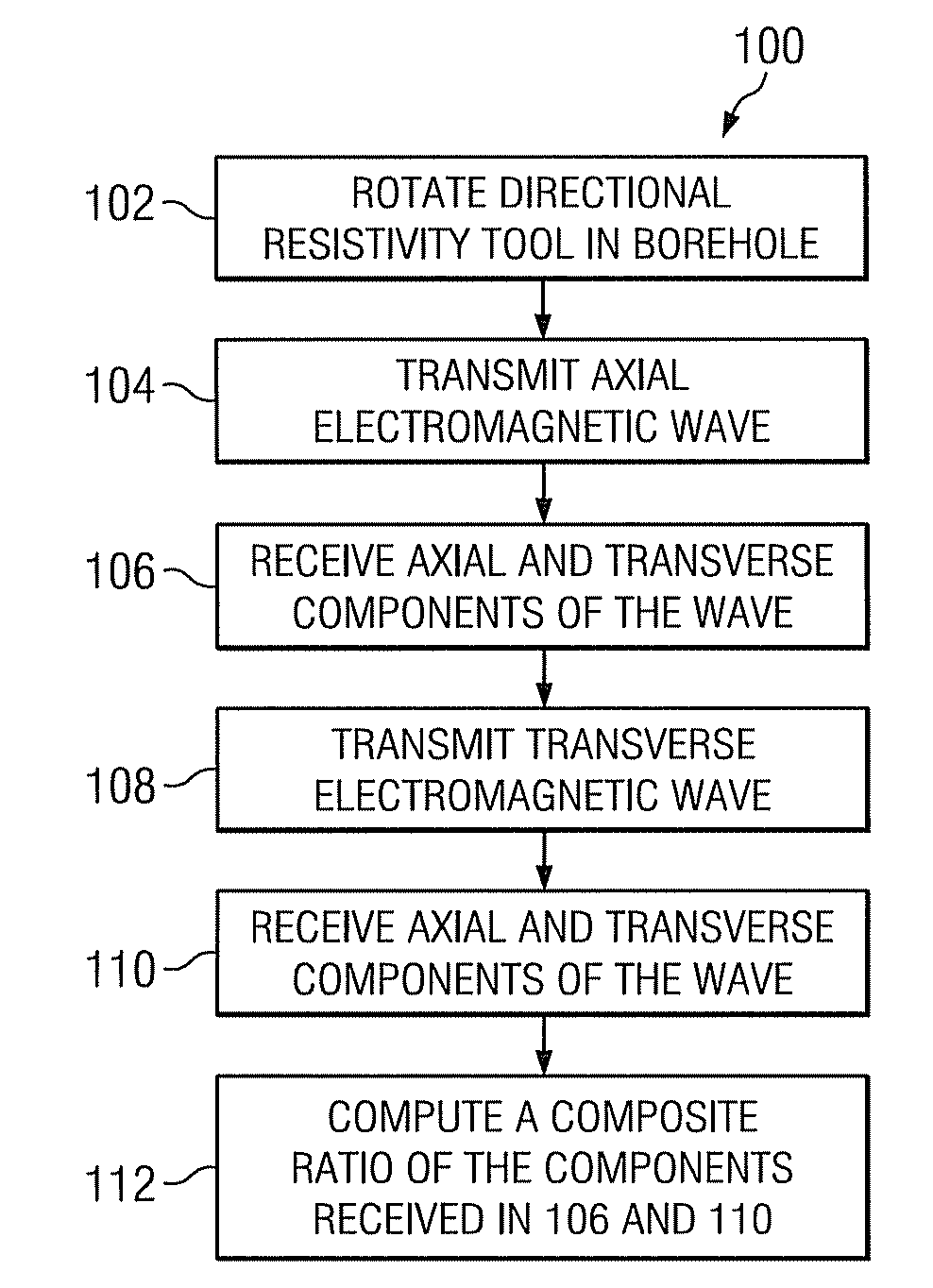
[0023]With reference to FIG. 1, exemplary method embodiment 100 in accordance with the present invention is depicted in flowchart form. In the exemplary embodiment depicted, a directional resistivity tool is rotated in a borehole at 102. As described in more detail below, the resistivity tool includes at least first and second transmitting antennae, one of which is configured to transmit substantially pure z-mode electromagnetic waves and the other of which is configured to transmit substantially pure x-mode electromagnetic waves. The tool further includes at least first and second receiving antennae longitudinally spaced from the transmitting antennae. One of the receiving antennae is configured to receive a substantially pure z-mode component of an electromagnetic wave and another is configured to receive a substantially pure x-mode component of an electromagnetic wave. The transmitting antennae may be fired (energized) sequentially (in either order) at 104 and 108, thereby transm...

embodiment 240

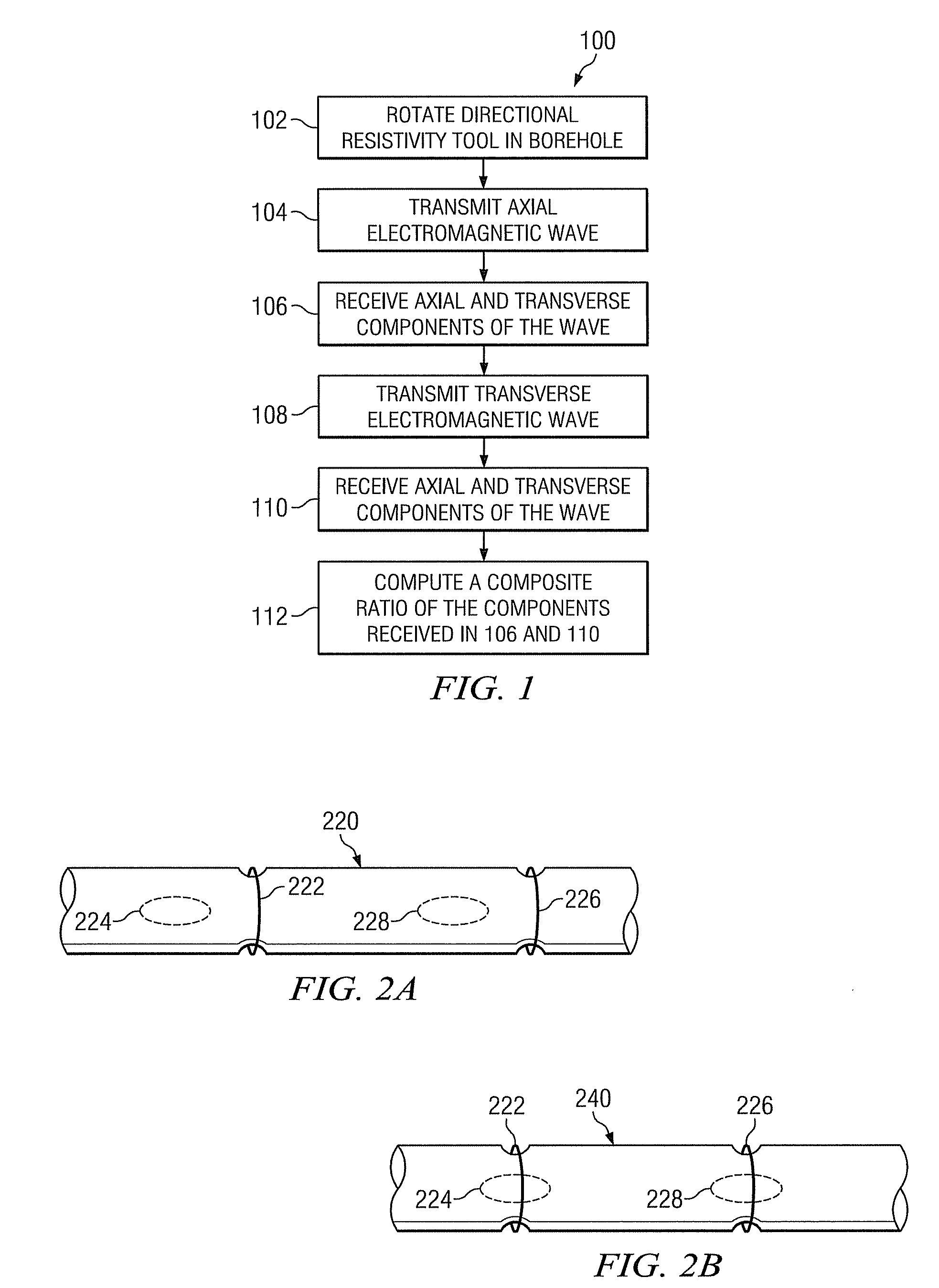
[0027]FIGS. 2A and 2B (collectively FIG. 2) depict exemplary EM directional resistivity tools 220 and 240 suitable for use with certain method embodiments in accordance with the present invention. Resistivity tool 220 (FIG. 2A) includes at least one axial transmitting antennae 222 and at least one transverse transmitting antenna 224 deployed on the tool body. The resistivity tool 220 further includes at least one axial receiving antenna 226 and at least one transverse receiving antenna 228 deployed on the tool body. In the exemplary embodiment depicted on FIG. 2A, each of the transmitting antennae 222 and 224 and the receiving antennae 226 and 228 are longitudinally spaced on the tool body. The transmitting antennae and the receiving antennae may also be collocated, for example, as depicted on FIG. 2B for tool embodiment 240. In FIG. 2B, the transmitting antennae are collocated and the receiving antennae are collocated. The invention is not limited in this regard. The transmitting a...


PUM


Abstract

A method for making directional resistivity measurements includes sequentially transmitting first and second axial and transverse electromagnetic waves in a borehole and receiving substantially pure axial and transverse components of each of the transmitted waves. A composite ratio of the received components is computed and may be utilized as an indicator of various formation parameters. The invention advantageously provides for the acquisition of compensated directional resistivity measurements.

Description

RELATED APPLICATIONS[0001]None.FIELD OF THE INVENTION[0002]The present invention relates generally to methods for making directional resistivity measurements of the electromagnetic properties of a subterranean borehole. More particularly, method embodiments of this invention include compensating directional resistivity measurements by computing a composite ratio of axial and transverse components of received electromagnetic waves.BACKGROUND OF THE INVENTION[0003]The use of electrical measurements in prior art downhole applications, such as logging while drilling (LWD), measurement while drilling (MWD), and wireline logging applications is well known. Such techniques may be utilized to determine a subterranean formation resistivity, which, along with formation porosity measurements, is often used to indicate the presence of hydrocarbons in the formation. For example, it is known in the art that porous formations having a high electrical resistivity often contain hydrocarbons, such as...

Claims


Application Information

Patent Timeline
IPC IPC(8): G01V3/12
CPCG01V3/30
Inventor STREINZ, CHRISTOPHER C.WANG, TSILI
Owner SCHLUMBERGER TECH CORP
Why Eureka
Try Eureka