Sample measurement device, sample measurement system and sample measurement method
- Summary
- Abstract
- Description
- Claims
- Application Information
AI Technical Summary
Benefits of technology
Problems solved by technology
Method used
Image
Examples
embodiment 1
1. Embodiment 1
[0096]A biosensor measurement system (sample measurement system) 100 pertaining to Embodiment 1 of the present invention will now be described. Blood is used here as the specimen (sample). The specific component to be measured is the glucose concentration.
[0097]1.1 Biosensor Measurement System 100
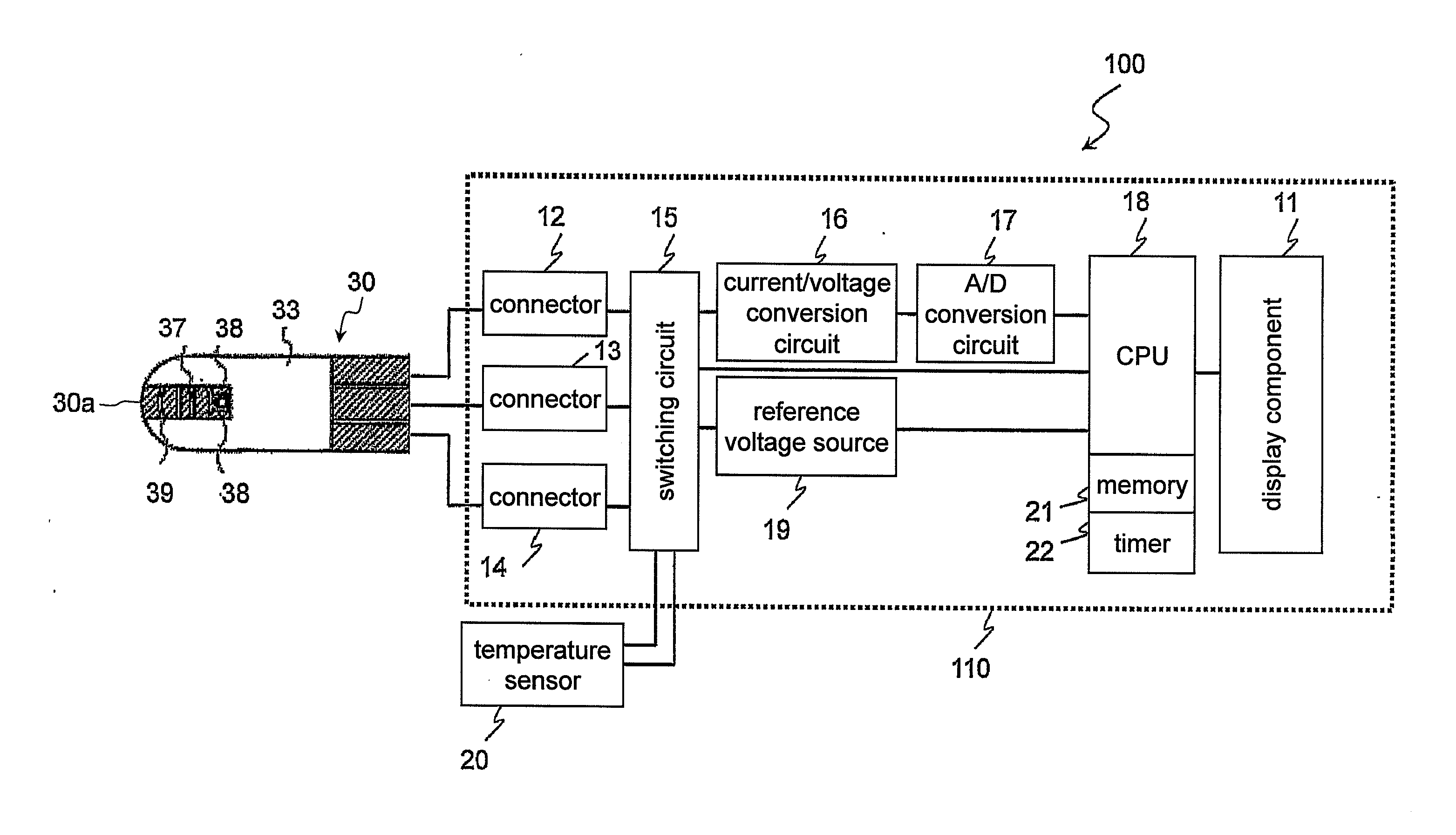
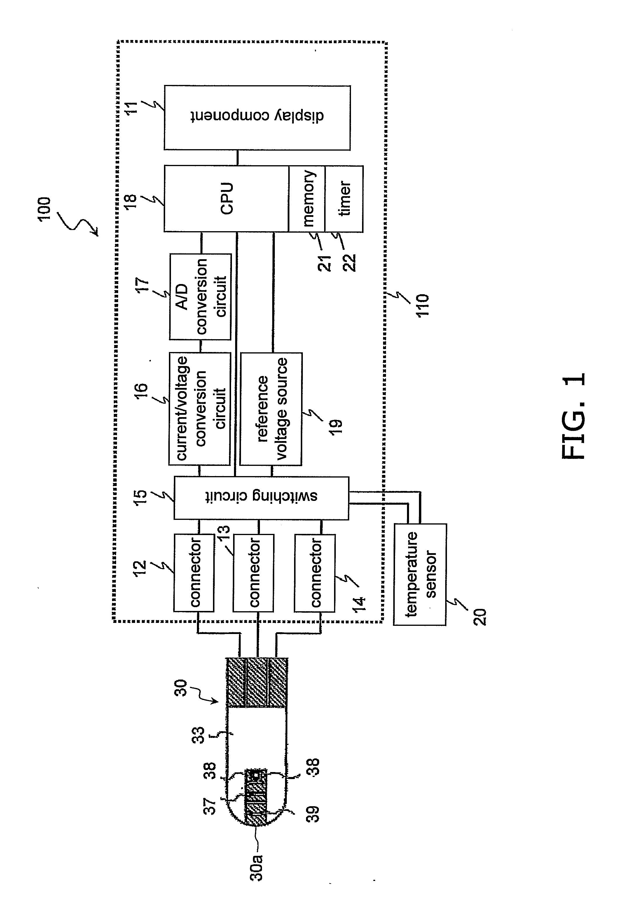
[0098]FIG. 1 is a simplified diagram of the constitution of the biosensor measurement system 100 in Embodiment 1. Those components that are the same as in the biosensor measuring system 700 in FIG. 12 are numbered the same in FIG. 1.
[0099]The biosensor measurement system 100 of Embodiment 1 comprises a biosensor 30 and a measuring device (sample measurement device) 110. The biosensor 30 is held directly in the hand of the user, and is mounted in the measuring device 110 to perform measurement. The configuration of the biosensor 30 is the same as that shown in FIG. 13, and will not be described again here.
[0100]1.2 Measuring Device 110
1.2.1 Configuration of Measuring Device 11...
embodiment 2
2. Embodiment 2
[0170]The biosensor measurement system (sample measurement system) 100 pertaining to Embodiment 2 of the present invention will now be described.
[0171]Those components that are the same as in Embodiment 1 will be numbered the same. Also, since the constitution of the biosensor measurement system and the measuring device is the same as that in Embodiment 1, it will not be described in detail again here.
[0172]2.1 Operation of Measuring Device 110
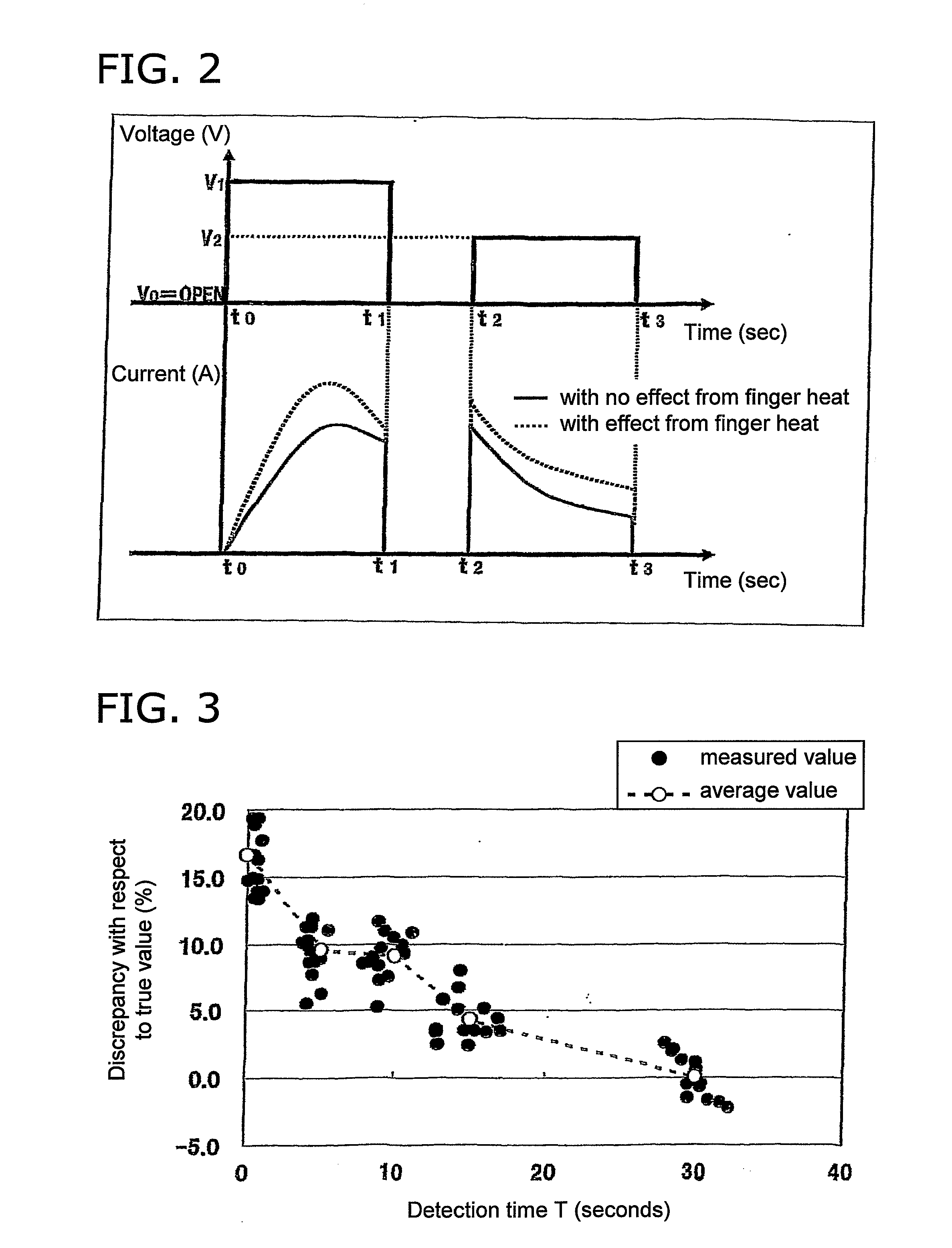
[0173]The measuring device 110 pertaining to Embodiment 2 (FIG. 1) differs from that in Embodiment 1 in that the applied voltage value for measuring (the set value for measuring) is changed on the basis of the detection time T from the mounting of the biosensor 30 to the measuring device 110 until the biosensor 30 detects that a specimen has been deposited.
[0174]FIG. 8 is a graph of the measurement profile in Embodiment 2, and the current response curve thus obtained. In this embodiment, in the third step the voltage V2 is lower...
modification examples
4. Modification Examples
[0203](1)
[0204]In Embodiments 1 and 2 above, the tables Tb1 and Tb2 are referred to in changing the set value (measurement time or applied voltage), but the set value may instead be calculated from a specific mathematical formula according to the detection time T or the measurement temperature.
[0205]Also, a calculation formula may be used that makes use of a coefficient or a parameter other than the detection time T or the measurement temperature.
(2)
[0206]In Embodiments 1 and 2 above, a case was discussed in which either measurement time or applied voltage is changed in the method for measuring the glucose concentration in blood deposited on the biosensor 30, but the present invention is not limited to this, and the same effect can be anticipated when both measurement time and applied voltage are changed.
(3)
[0207]In Embodiments 1 and 2 above, it was decided that no extension of the measurement time was necessary when the detection time T exceeded 20 seconds, ...
PUM
| Property | Measurement | Unit |
|---|---|---|
| Temperature | aaaaa | aaaaa |
| Temperature | aaaaa | aaaaa |
| Temperature | aaaaa | aaaaa |
Abstract
Description
Claims
Application Information
 - R&D
- Intellectual Property
- Life Sciences
- Materials
- Tech Scout
- Unparalleled Data Quality
- Higher Quality Content
- 60% Fewer Hallucinations
Browse by: Latest US Patents, China's latest patents, Technical Efficacy Thesaurus, Application Domain, Technology Topic, Popular Technical Reports.
© 2025 PatSnap. All rights reserved.Legal|Privacy policy|Modern Slavery Act Transparency Statement|Sitemap|About US| Contact US: help@patsnap.com


