Monobit Based Low Cost High Performance Radar Warning Receiver

a radar warning and low-cost technology, applied in the field of radar warning receivers, can solve the problems of large market for these devices, high incoming rf signal, and high cost of parts, and achieve the effects of small and inexpensive, low cost, and substantial suppression of nois

Active Publication Date: 2010-11-11
BAE SYST INFORMATION & ELECTRONICS SYST INTERGRATION INC
View PDF9 Cites 32 Cited by
  • Summary
  • Abstract
  • Description
  • Claims
  • Application Information

AI Technical Summary

Benefits of technology

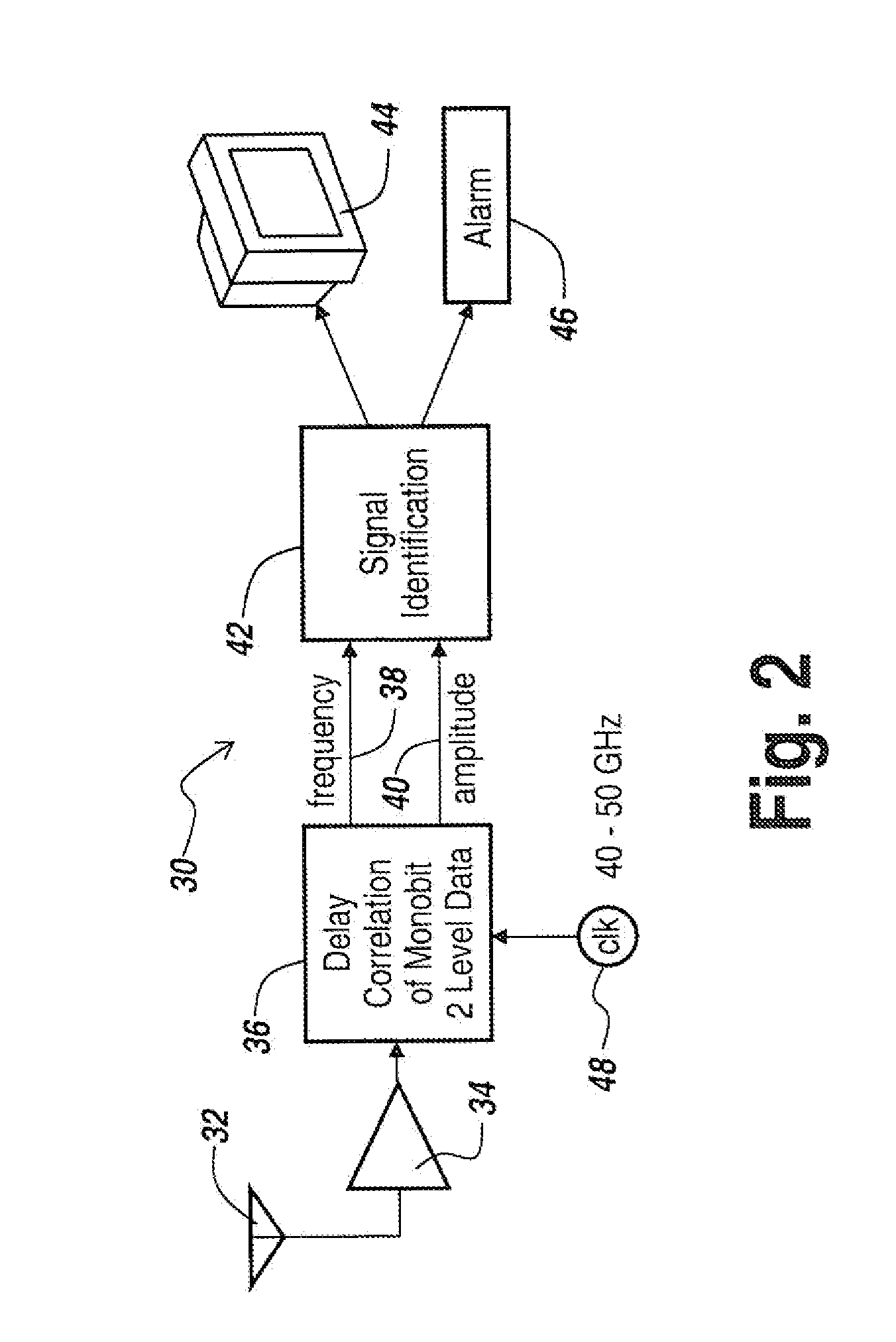
[0015]It is now possible to do a more sophisticated job of signal detection using digital signal processing techniques that permit detection and classification of very small signals, even below the noise level. This is done by a monobit sampling radar warning receiver that has all the bandwidth and functionality of older radar warning receiver designs while enabling better sensitivity and more accurate performance at substantially reduced cost.

Problems solved by technology

Thus, there is not a large market for these devices and the parts are becoming very expensive.
This means that the incoming RF signal is amplified so much that the amplifier runs out of head room and hits so-called stops.
The problem with the prior art radar warning receivers is that they are very expensive not only from an initial cost point of view, but also very expensive to maintain.
Moreover, they do not work particularly well as the signal environment gets more and more complex.
These types of signals do not lend themselves to detection by the typical radar warning receiver described above since the probability of detecting individual noninterfering pulses is low due to the high duty cycles and the fact that their amplitude is less.
The high cost of these systems comes form the number of custom broadband components and precision delay lines and filters that are required.
When working in the RF domain, it is therefore problematic to provide a cost-effective radar warning receiver.
However, if one could convert the analog signals into a digital format then the costs go along with Moore's Law.
This means that the size and the cost of the equipment goes down as time progresses.
However, RF technology does not follow Moore's Law.
Also as part of the prior art, a lot of effort has been expended in converting signals into the digital domain.
The problem with these systems is that while they handle very complex environments which are typically encountered for instance at 20,000 feet for an aircraft, they are very expensive to build because they still involve many channels of RF operating in parallel to cover multi-GHz at any instant.
This device is limited to operating on only the largest of signals that are present in the environment at any instant of time and does not include any signal detection capability.
This in turn results in only the moderate level of performance that one would see with the older style radar warning receivers since it did not include any additional functionality.

Method used


Image

  • Monobit Based Low Cost High Performance Radar Warning Receiver
  • Monobit Based Low Cost High Performance Radar Warning Receiver
  • Monobit Based Low Cost High Performance Radar Warning Receiver

Examples


Embodiment Construction

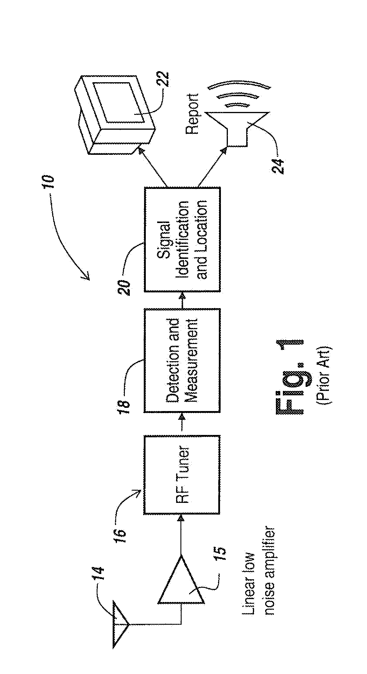
[0052]Referring now to FIG. 1, prior art radar warning receivers 10 typically include an RF tuner which selects a more limited region of frequency for processing at any instant of time. The outputs of the RF tuners are coupled to a detection and measurement module 18, with the output of module 18 being applied to a signal identification and location module 20 to output either visually at a display 22 or orally at a speaker 24 the fact of the existence of a threat radar signal.

[0053]In the FIG. 1 analog embodiment, the radar warning receiver looks at multiples of the measurements from the detected amplitude of the incoming signals to determine the existence of a threat type of radar that is observing the platform in which the radar warning receiver is placed.

[0054]It will be appreciated that the RF tuners in essence employ a number of delay lines that act as filters, each responsive to a different frequency. Thus one could use a bank of filters to provide an instantaneous frequency m...


PUM


Abstract

A radar warning receiver is implemented in low cost integrated circuit form utilizing only one analog component, namely a limiting amplifier. By taking the output of the limiting amplifier and utilizing monobit sampling of the output it has been found that one can provide an integrated circuit single chip radar warning receiver using delay correlation to extract frequency, amplitude and modulation type from signals at or below the noise level.

Description

RELATED APPLICATIONS[0001]This Application claims rights under 35 USC §119(e) from U.S. Application Ser. No. 61 / 107,552 filed Oct. 22, 2008, the contents of which are incorporated herein by reference.FIELD OF THE INVENTION[0002]This invention relates to radar warning receivers and more particularly to a digitally-based wideband system for detecting the presence and identity of threat radars.BACKGROUND OF THE INVENTION[0003]In the past, typical radar warning receivers detect RF energy over multi-GHz bandwidths using a log video detector. Separately they would determine the frequency of the energy using a bank of analog filters or an Instantaneous Frequency Measurement (IFM) unit. IFMs employ multiple analog delay lines coupled with RF mixers and other components to create an estimate of the frequency of the RF energy that was detected in the log video detector.[0004]As time has progressed, while these parts are not necessarily complex, they are very unique to this type of application...

Claims


Application Information

Patent Timeline
Patent Type & Authority Applications(United States)
IPC IPC(8): G01S13/88
CPCG01S7/285G01S7/021
Inventor HUGGETT, JAMES M.
Owner BAE SYST INFORMATION & ELECTRONICS SYST INTERGRATION INC
Why Eureka
Try Eureka