Power distribution systems

a technology of power distribution system and power distribution voltage, applied in the direction of dc network load balancing, emergency protective arrangements for limiting excess voltage/current, transmission, etc., can solve the problems of regulated response subject to significant disparities, fault current may exceed the capability of available protective switchgear, and often become problematic, so as to improve the ability to design freedom, increase intelligence and automation, and stabilize the effect of distribution voltag

Active Publication Date: 2010-11-11
GE POWER CONVERSION
View PDF7 Cites 53 Cited by
  • Summary
  • Abstract
  • Description
  • Claims
  • Application Information

AI Technical Summary

Benefits of technology

[0028]In general terms, the power distribution system includes at least one power source whose output current is rectified or naturally produces dc current. The output current is preferably limited by fast acting means (such as a power converter, for example) according to the power source foldback and stabilizing characteristic that initially causes maximum prospective fault current to be much larger than for a conventional impedance-limited case, and that subsequently causes the output current to be commutated in a coordinated action. The power source foldback and stabilizing characteristic also facilitates current sharing between parallel-connected power sources by incorporating a steady state droop component. Moreover, the power source foldback and stabilizing characteristic also facilitates the stabilization of the distribution voltage by incorporating an appropriate transient response that is superimposed on the steady state droop component.
[0072]The load voltage may be ramped up to the desired operating point according to a time-variable ramp rate that is specified according to the dynamic capability of the at least one power source and the need to allow the at least one power source to progressively supply an increasing proportion of the total load current in the power distribution system to minimize resultant voltage transients within the power distribution system.

Problems solved by technology

As the total installed power rating is increased and / or distribution voltage is reduced, the resulting fault current may exceed the capability of the available protective switchgear.
Moreover, these characteristics are greatly influenced by the type of prime movers (diesel engine D or turbine T, for example) that is coupled to the generator and their resultant coupled governed and regulated responses may be subject to significant disparities.
When a group of generators G is connected to a point of common coupling then disparities often become problematic, particularly during the switching of passive circuits such as filters and transformers and during load transients.
Synchronization and load transfer between individual islands is complicated, particularly when they have different degrees of harmonic pollution and when the disparities mentioned above are present.
Because it is a complex ac system it is recognized that it is very difficult to damp the inevitable resonant modes between stray and intentional impedances that affect such a power distribution system.
Once an ac distribution frequency (i.e., the frequency of the ac current carried by the various ac busbars in the FEP system) has been chosen then this will greatly influence the generator topology and ultimately places limits on the shaft speed of the prime mover.
In many cases, this will adversely affect the size and performance of the generator and the prime mover.
Although these LVDC systems derive their dc current from MVAC current supplies via current limited power electronics, they rely on dc circuit breakers (DCCB) to interrupt significant fault currents.
The DCCBs must therefore interrupt fault current by electromechanically causing contacts to open, thereby causing arc voltage to be generated between the contacts.
As the fault current approaches final interruption, the arc voltage will experience a transient increase that is known to stress components that are connected to the SSDS and which generates electromagnetic interference (EMI).

Method used


Image

  • Power distribution systems
  • Power distribution systems
  • Power distribution systems

Examples


Embodiment Construction

[0111]Although the following description is directed to a power distribution system for marine applications, and in particular to a power distribution system that is highly suitable for naval ships and submarines, it will be readily understood that a similar topology and control method can be used in other sorts of power distribution systems such as land-based or aircraft-based systems, for example.

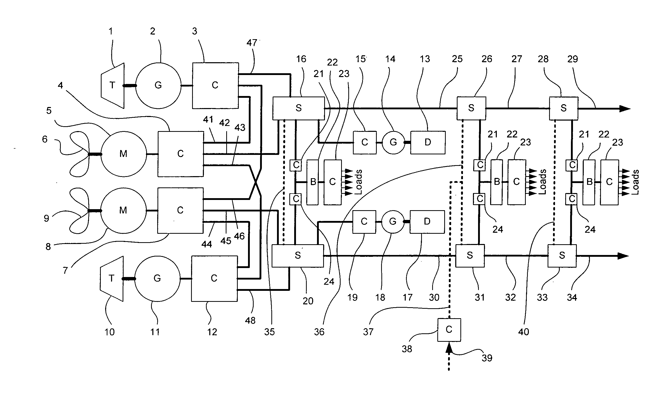
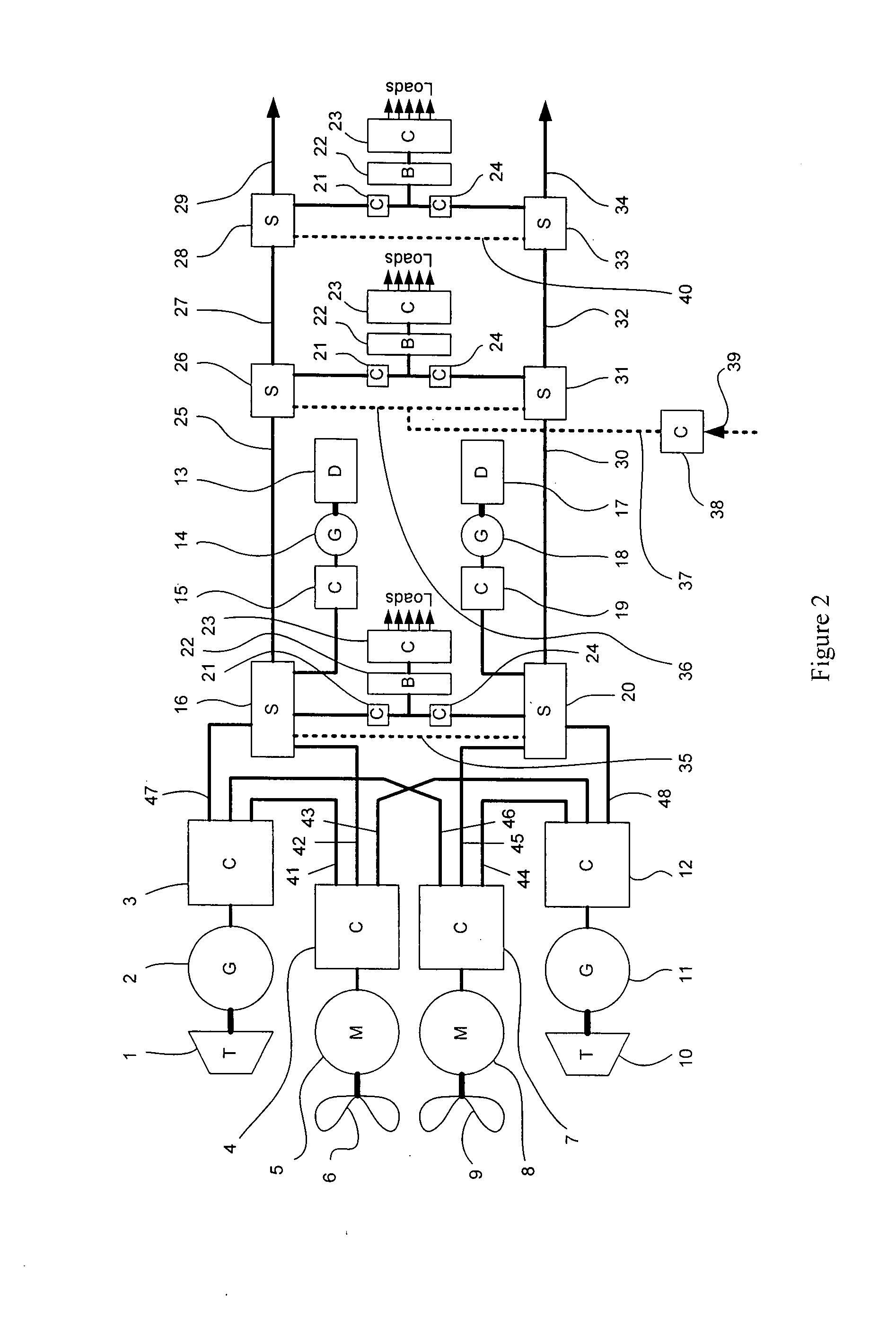
[0112]The basic topology of a power distribution system according to the present invention will now be described with reference to FIG. 2. It should be appreciated that all of the inputs, outputs, terminals and interconnections of FIG. 2 are of double pole direct current type.

[0113]A first Propulsion Power Generation System (PPGS) includes a turbine 1 that drives a generator 2 to supply power to an output converter 3. Similarly, a second PPGS includes a turbine 10 that drives a generator 11 to supply power to an output converter 12. A first Propulsion Drive System (PDS) includes a propell...


PUM


Abstract

A power distribution system that can be used in naval ships and submarines includes a first power generation system including at least one power source for supplying power to a first service distribution system that includes at least one dc distribution busbar for carrying a distribution voltage and a distribution current and at least one switchboard that includes protective switchgear with contacts. A zonal power distribution sub-system includes a zonal power supply unit for supplying power to at least one electrical load and a zonal energy store connected to the at least one switchboard of the first service distribution system for supplying power to the zonal power supply unit. The at least one power source is regulated according to a power source foldback and stabilizing characteristic and a power source starting characteristic. The at least one electrical load is regulated according to a load shedding and stabilizing characteristic.

Description

FIELD OF THE INVENTION[0001]The present invention relates to a power distribution system, and in particular to a “smart” power distribution system that can be used for marine power and propulsion systems. The power distribution system enables a marine power and propulsion system to achieve maximum power density, efficiency and stability and facilitates future technology insertions by means of a modular approach and standard interfaces.BACKGROUND OF THE INVENTION[0002]In conventional marine power and propulsion systems that employ full electric propulsion (FEP), fault current magnitude-time discrimination is used to enable protective switchgear to interrupt over-current faults in particular sub-circuits while causing the minimum practical disruption to all other sub-circuits. Such FEP systems are said to employ the “power station principle” where the aim is to adapt the power generation capacity that is on-line at any particular time to the total load that is being drawn at that time...

Claims


Application Information

Patent Timeline
Patent Type & Authority Applications(United States)
IPC IPC(8): H02H3/08
CPCB63H21/20B63H23/24H02J4/00H02H7/268H02J1/14H01H33/596H02J2310/42H02H3/025H02H3/06H02J1/00H02J11/00
Inventor CRANE, ALLAN DAVID
Owner GE POWER CONVERSION
Why Eureka
Try Eureka