Marine power distribution and propulsion systems

a technology of power distribution and propulsion system, which is applied in the direction of marine propulsion, vessel construction, propulsive elements, etc., can solve the problems of large disparities in regulated responses, large fault currents, and often becoming problemati

Inactive Publication Date: 2010-11-11
CONVERTEAM TECH LTD
View PDF2 Cites 36 Cited by
  • Summary
  • Abstract
  • Description
  • Claims
  • Application Information

AI Technical Summary

Benefits of technology

[0025]In general terms, the power distribution system includes at least one power source whose output current is rectified or naturally produces dc current. The output current is preferably limited by fast acting means (such as a power converter, for example) according to a power source foldback and stabilizing characteristic that initially causes maximum prospective fault current to be much larger than for a conventional impedance-limited case, and that subsequently causes the output current to be commutated in a coordinated action. The power source foldback and stabilizing characteristic also facilitates current sharing between parallel-connected power sources by incorporating a steady state droop component. Moreover, the power source foldback and stabilizing characteristic also facilitates the stabilization of the distribution voltage by incorporating an appropriate transient response that is superimposed on the steady state droop component.
[0068]The marine power distribution and propulsion system may be configured such that power can be supplied to the first service distribution system through the at least one switchboard by one or more of the following: the first power generation system, the zonal energy store of the zonal power distribution sub-system, a propulsion drive system operating in a regenerative mode, a propulsion power generation system, and a remote power supply system such as a shore-based power supply, for example. This provides a considerable degree of redundancy.

Problems solved by technology

As the total installed power rating is increased and / or distribution voltage is reduced, the resulting fault current may exceed the capability of the available protective switchgear.
Moreover, these characteristics are greatly influenced by the type of prime movers (diesel engine D or turbine T, for example) that is coupled to the generator and their resultant coupled governed and regulated responses may be subject to significant disparities.
When a group of generators G is connected to a point of common coupling then disparities often become problematic, particularly during the switching of passive circuits such as filters and transformers and during load transients.
Synchronization and load transfer between individual islands is complicated, particularly when they have different degrees of harmonic pollution and when the disparities mentioned above are present.
Because it is a complex ac system it is recognized that it is very difficult to damp the inevitable resonant modes between stray and intentional impedances that affect such a power distribution system.
Once an ac distribution frequency (i.e. the frequency of the ac current carried by the various ac busbars in the FEP system) has been chosen then this will greatly influence the generator topology and ultimately places limits on the shaft speed of the prime mover.
In many cases, this will adversely affect the size and performance of the generator and the prime mover.
Although these LVDC systems derive their dc current from MVAC current supplies via current limited power electronics, they rely on dc circuit breakers (DCCB) to interrupt significant fault currents.
The DCCBs must therefore interrupt fault current by electromechanically causing contacts to open, thereby causing arc voltage to be generated between the contacts.
As the fault current approaches final interruption, the arc voltage will experience a transient increase that is known to stress components that are connected to the SSDS and which generates electromagnetic interference (EMI).

Method used


Image

  • Marine power distribution and propulsion systems
  • Marine power distribution and propulsion systems
  • Marine power distribution and propulsion systems

Examples


Embodiment Construction

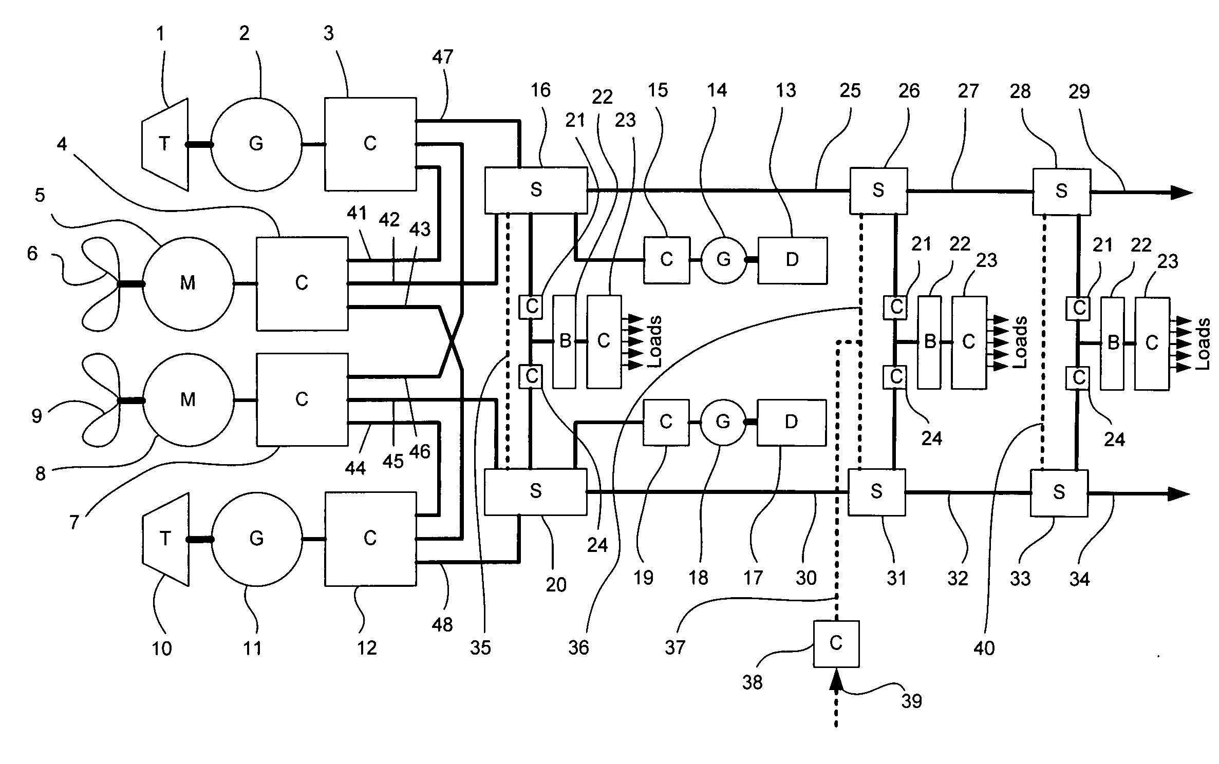
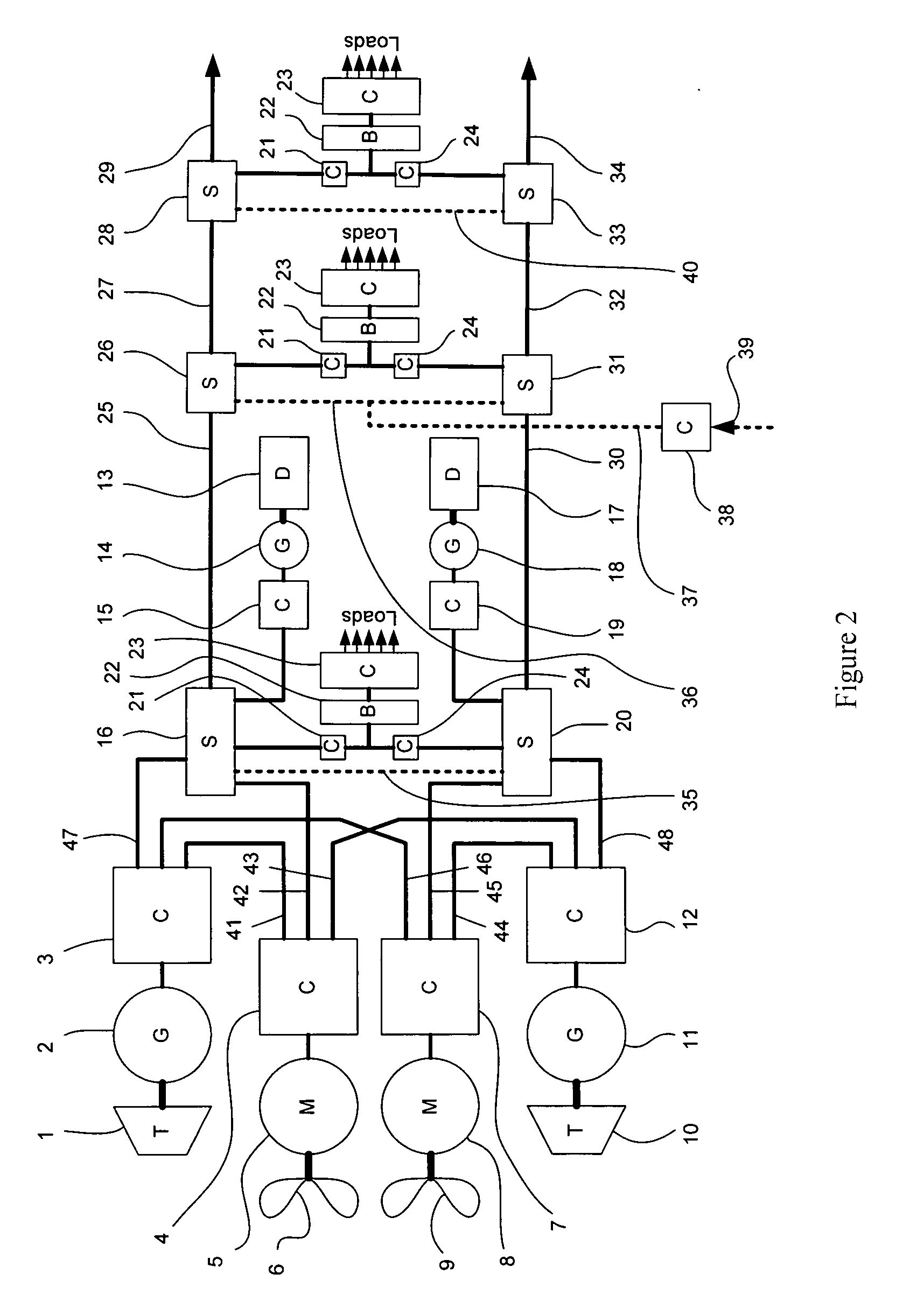
[0078]The basic topology of a marine power distribution and propulsion system according to the present invention will now be described with reference to FIG. 2. It should be appreciated that all of the inputs, outputs, terminals and interconnections of FIG. 2 are of double pole direct current type.

[0079]A first Propulsion Power Generation System (PPGS) includes a turbine 1 that drives a generator 2 to supply power to an output converter 3. Similarly, a second PPGS includes a turbine 10 that drives a generator 11 to supply power to an output converter 12. A first Propulsion Drive System (PDS) includes a propeller 6 that is driven by a propulsion motor 5 whose power flow is regulated by a propulsion converter 4. Similarly, a second PDS comprises a propeller 9 that is driven by a propulsion motor 8 whose power flow is regulated by a propulsion converter 7. The output converters 3 and 12 each have three sets of output terminals and the propulsion converters 4 and 7 each have three sets ...


PUM


Abstract

A power distribution system that can be used in naval ships and submarines includes a first propulsion drive system including a propulsion motor having superconducting (preferably high temperature superconducting (HTS)) rotor windings and a power converter. A first propulsion power generation system supplies power to the first propulsion drive system and includes a generator having superconducting (preferably HTS) rotor windings and a power converter. A first power generation system includes a power source for supplying power to a first service distribution system that includes a dc distribution busbar (optionally implemented using HTS cabling or busbar) for carrying a distribution voltage and a distribution current, and a switchboard that includes protective switchgear with contacts. A power converter is used to connect the power source to the switchboard. The power converters are regulated according to a power source foldback and stabilizing characteristic. An electric load is supplied with power from a zonal power supply unit that forms part of a zonal power distribution sub-system. The electric load and the propulsion motor are regulated according to a load shedding and stabilizing characteristic.

Description

CROSS REFERENCE TO RELATED APPLICATION[0001]This application is a continuation-in-part of U.S. patent application Ser. No. 11 / 974,569 filed Oct. 15, 2007.FIELD OF THE INVENTION[0002]The present invention relates to a marine power distribution and propulsion system, and in particular to a system that can achieve maximum power density, efficiency and stability and facilitates future technology insertions by means of a modular approach and standard interfaces.BACKGROUND OF THE INVENTION[0003]In conventional marine power distribution and propulsion systems that employ full electric propulsion (FEP), fault current magnitude-time discrimination is used to enable protective switchgear to interrupt over-current faults in particular sub-circuits whilst causing the minimum practical disruption to all other sub-circuits. Such FEP systems are said to employ the “power station principle” where the aim is to adapt the power generation capacity that is on-line at any particular time to the total l...

Claims


Application Information

Patent Timeline
Patent Type & Authority Applications(United States)
IPC IPC(8): B63H21/17
CPCY02T90/38B63H23/24Y02T90/40
Inventor CRANE, ALLAN DAVIDLEWIS, CLIVE
Owner CONVERTEAM TECH LTD
Why Eureka
Try Eureka