Suppressor and ion chromatograph employing the same

a technology of ion chromatograph and suppressor, which is applied in the field of suppressor and ion chromatograph, can solve the problems of affecting the performance of individual suppressors, affecting the performance of ion chromatograph, and affecting the effect of liquid leakag

Active Publication Date: 2010-11-11
SHIMADZU CORP
View PDF5 Cites 15 Cited by
  • Summary
  • Abstract
  • Description
  • Claims
  • Application Information

AI Technical Summary

Benefits of technology

[0020]In a suppressor according to the present invention and an ion chromatograph employing such a suppressor, one side of an ion-exchange membrane opposite to the other side of the ion-exchange membrane, which is in contact with an eluate channel, is supported by an ion-exchange membrane support member, and the other side of the ion-exchange membrane opposite to the one side of the ion-exchange membrane, which is in contact with a regenerant channel, is also supported

Problems solved by technology

This, however, increases the load on the ion-exchange membrane, which may cause disadvantages, such as leakage of liquid from parts fixing the ion-exchange membrane.
Further, in a case where the filler is an ion-exchange resin, there is a case where a dif

Method used


Image

  • Suppressor and ion chromatograph employing the same
  • Suppressor and ion chromatograph employing the same
  • Suppressor and ion chromatograph employing the same

Examples


first embodiment

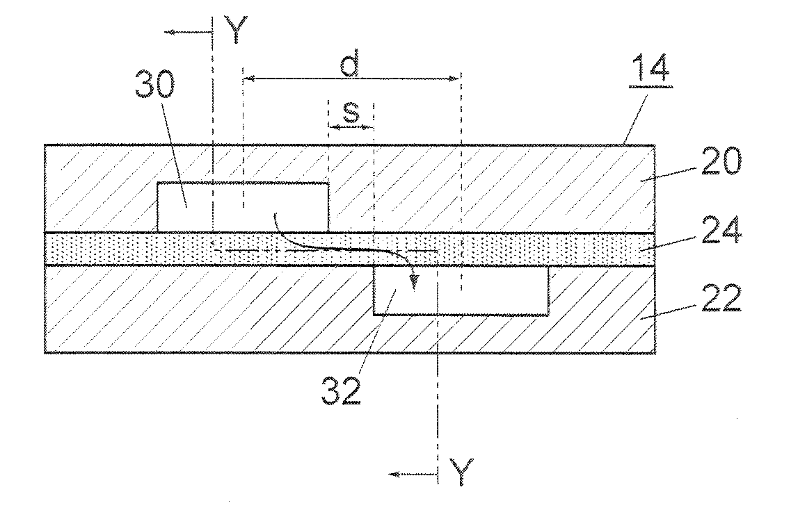
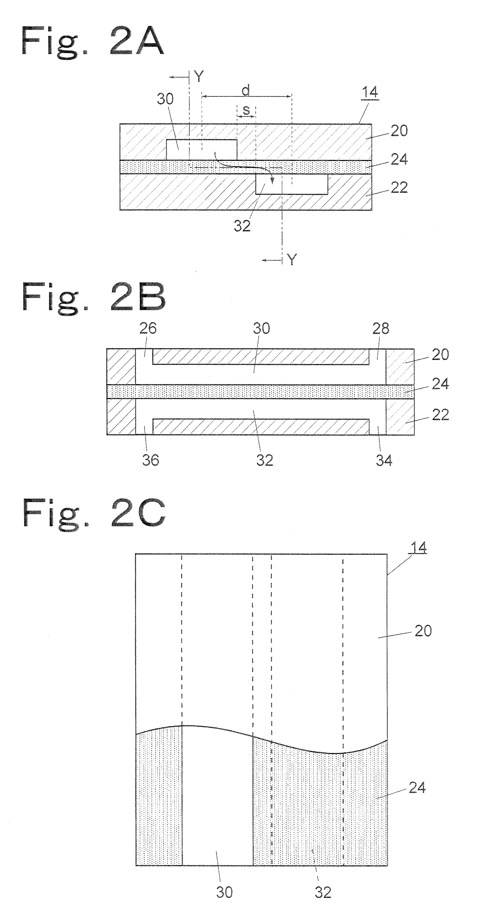
[0033]In a case where the ion chromatograph is intended to analyze anions, the suppressor 14 is used to remove cations contained in an eluate through ion exchange. FIGS. 2A to 2C show the suppressor 14 as a suppressor according to the present invention. The suppressor 14 includes a cover 20 and a base 22 as base bodies. The cover 20 and base 22 are made of an inert material to which ions are not adsorbed and from which ions are not eluted. Examples of such an inert material include acrylic resins and PEEK (polyether ether ketone) resins. Between the cover 20 and the base 22, an ion-exchange membrane 24 is interposed and fixed. The cover 20 has an eluate channel 30 formed therein. The eluate channel 30 has an inlet 26 and an outlet 28 and allows an eluate discharged from the separation column 2 to flow therethrough so that the eluate is brought into contact with the ion-exchange membrane 24. The base 22 has a regenerant channel 32 formed therein. The regenerant channel 32 has an inle...

second embodiment

[0042]In the suppressor ionic functional groups of the ion-exchange membrane 24 are supplied from a regenerant flowing through both the regenerant channels 32a and 32b, and nontarget ions contained in an eluate flowing through the eluate channel 30 are removed by exchanging them for ionic functional groups supplied from a regenerant flowing through the regenerant channels 32a and 32b.

[0043]FIG. 4 shows a suppressor according to a third embodiment of the present invention. The suppressor according to the third embodiment has an ion-exchange membrane 44 in addition to the ion-exchange membrane 24 so that these two ion-exchange membranes 24 and 44 are in contact with two different surfaces of the eluate channel 30. The eluate channel 30 is provided as a through-groove in a base body 20a interposed between the two ion-exchange membranes 24 and 44, and has a flat rectangular sectional shape. One of the two opposed sides of the eluate channel 30 is in contact with the ion-exchange membr...

third embodiment

[0048]As described above, in the third embodiment shown in FIG. 4, two regenerant channels are in contact with each of the two ion-exchange membranes 24 and 44. However, one regenerant channel may be in contact with one of the two ion-exchange membranes and the other two regenerant channels may be in contact with the other ion-exchange membrane.

[0049]FIG. 5 shows a two-stage suppressor according to another embodiment of the present invention in which the two suppressors according to any one of the above embodiments are connected in series along the flow of a column eluate. More specifically, a suppressor 14a and a suppressor 14b are arranged along an eluate channel 9 on the upstream side and the downstream side, respectively. The eluate outlet of the upstream suppressor 14a is connected to the eluate inlet of the downstream suppressor 14b through a channel 50. An outlet 28 of the downstream suppressor 14b is connected to the electrical conductivity measurement cell 10.

[0050]Hereinbe...


PUM


Abstract

A suppressor which comprises: an ion-exchange membrane; an eluate channel which is in contact with one side of the ion-exchange membrane, serves as a channel through which an eluate discharged from a separation column flows, and has inside no obstacle to the flow; a regenerant channel which is in contact with the other side of the ion-exchange membrane, serves as a channel through which a regenerant for regenerating ionic functional groups of the ion-exchange membrane flows, has been disposed so that the regenerant channel has no region facing the eluate channel and extends in parallel to the eluate channel in such a nearby position that the ionic functional groups can move through the ion-exchange membrane, and has inside no obstacle to the flow; and an ion-exchange membrane support member which is in contact at least with that region on one side of the ion-exchange membrane which is opposed to the regenerant channel and with that region on the other side of the ion-exchange membrane which is opposed to the eluate channel to thereby support the ion-exchange membrane with wall surfaces.

Description

BACKGROUND OF THE INVENTION[0001]1. Field of the Invention[0002]The present invention relates to an ion chromatograph for separation and analysis of inorganic ions or organic ions contained in a sample solution and a suppressor for suppressing the background electrical conductivity of an eluate discharged from a separation column of such an ion chromatograph.[0003]2. Description of the Related Art[0004]In an ion chromatograph, a sample is introduced into a separation column to separate it into component ions, and then the component ions are detected by measuring the electrical conductivity of an eluate discharged from the separation column in an electrical conductivity measurement cell. In order to achieve high-sensitive measurement, a suppressor is provided between the separation column and the detector. The suppressor removes nontarget ions contained in an eluate discharged from the separation column to reduce the electrical conductivity of the eluate.[0005]As such a suppressor, o...

Claims


Application Information

Patent Timeline
IPC IPC(8): G01N30/02B01D59/30G01N27/06
CPCG01N2030/965G01N30/96
Inventor HORIIKE, SHIGEYOSHI
Owner SHIMADZU CORP
Why Eureka
Try Eureka