Barrel type plunger for use with a needle-retractable safety syringe and the syringe using the same
- Summary
- Abstract
- Description
- Claims
- Application Information
AI Technical Summary
Benefits of technology
Problems solved by technology
Method used
Image

Examples
embodiment 1
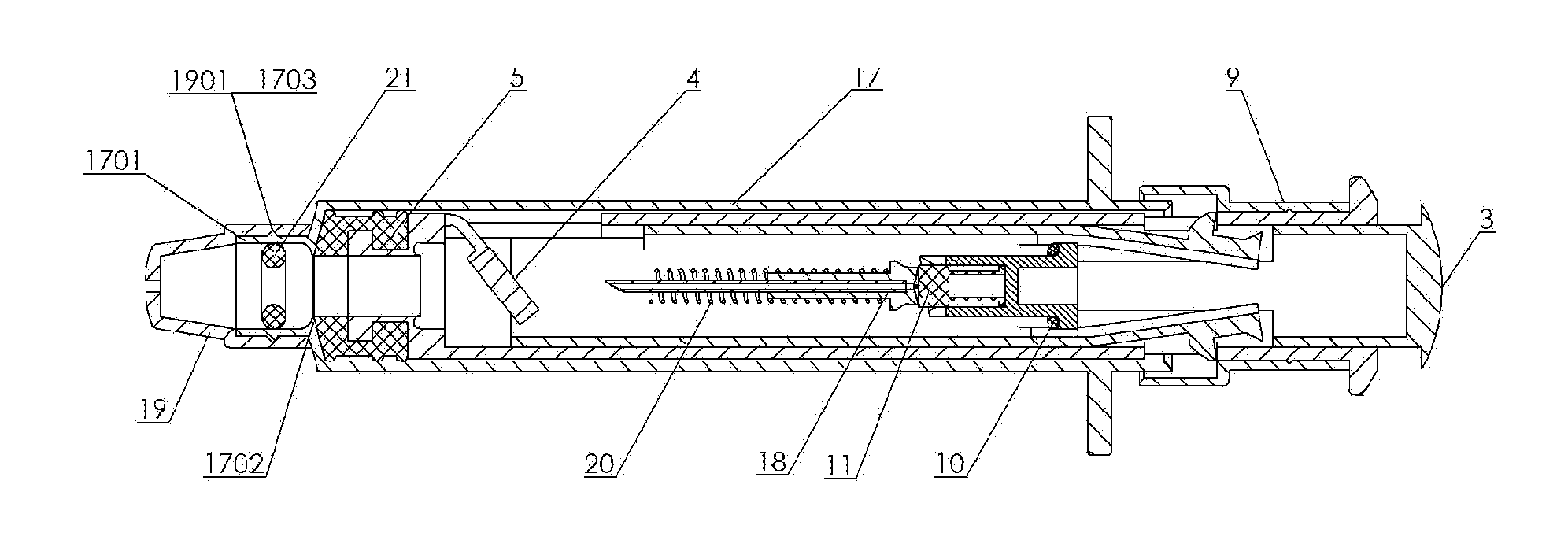
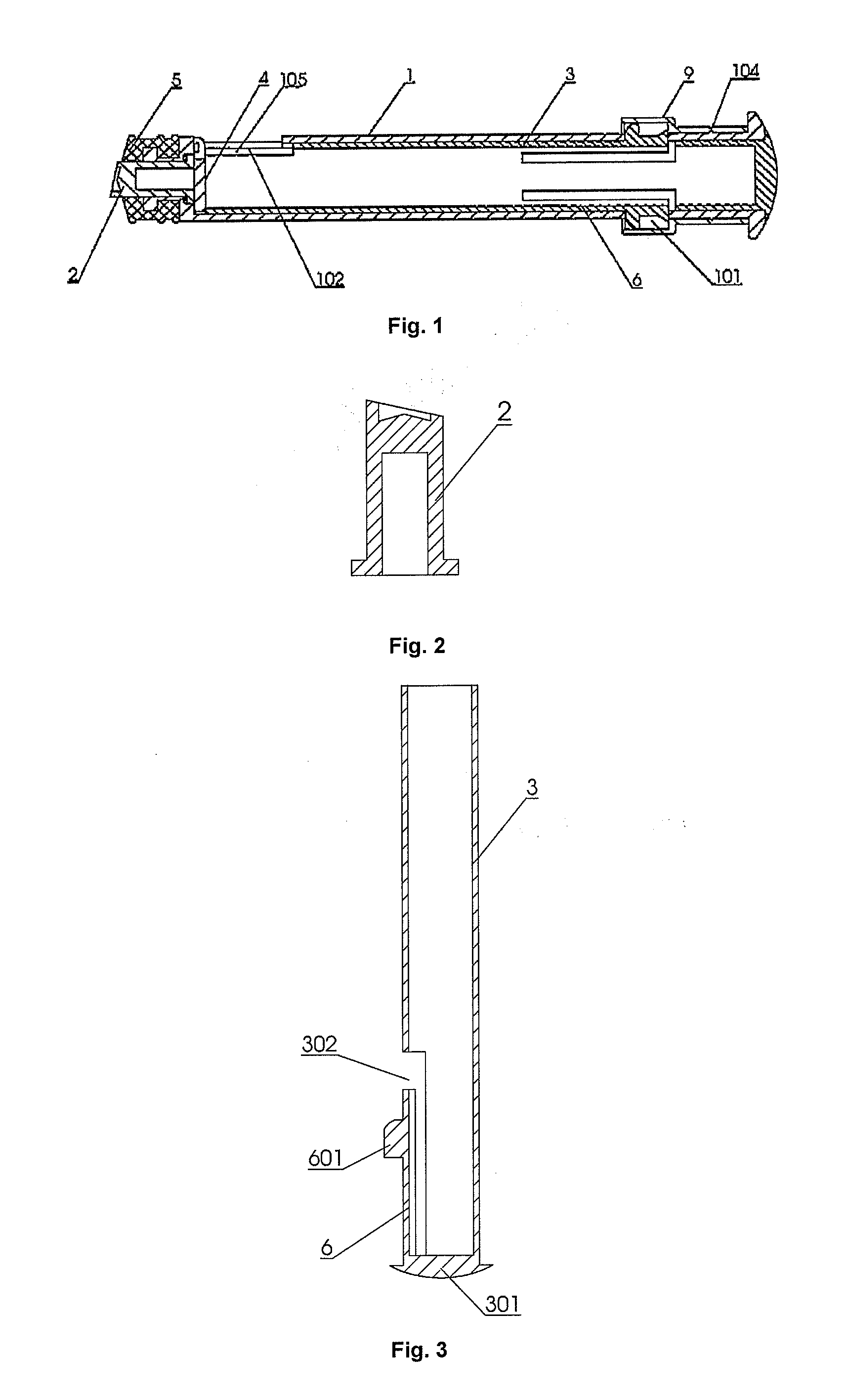
[0078]As shown in FIGS. 1, 2, 910 and 17, the improved barrel type plunger for use with a needle-retractable safety syringe according to the embodiment 1 comprises a barrel 1, a needle retracted trigger and a supporting member 3. A head portion of the barrel 1 is fitted with a sealing rubber pad 5.
[0079]The needle retracted trigger is a pushing post 2 having a closed front portion. After the assembly, the front end of the pushing post 2 is projected beyond an opening of the barrel cavity formed at the front end of said barrel 1 and the sealing rubber pad 5. Also, the projected portion is in a shape of a tubular structure with a flush end or in a shape of a tubular structure having an end with longitudinally extending gear-like projections.
[0080]A slotted hole 102 is provided at a wall of the front portion of said barrel 1. In the slotted hole 102, a bearing piece 4 is provided therein, one end of which is connected to the front side wall of said slotted hole 102. During the assembly...
embodiment 2
[0089]As shown in FIGS. 1, 2, 7, 8 and 17, the barrel type plunger for use with the needle-retractable safety syringe according to the present embodiment is substantially the same as that of embodiment 1. The differences between the embodiments 1 and 2 only lie in that, in the present embodiment, there only is one window 101 provided on the wall of the barrel 1 and one opening 302 provided on the wall of the barrel-like supporting member 3, respectively, and there also only is one flexible rib 6.
embodiment 3
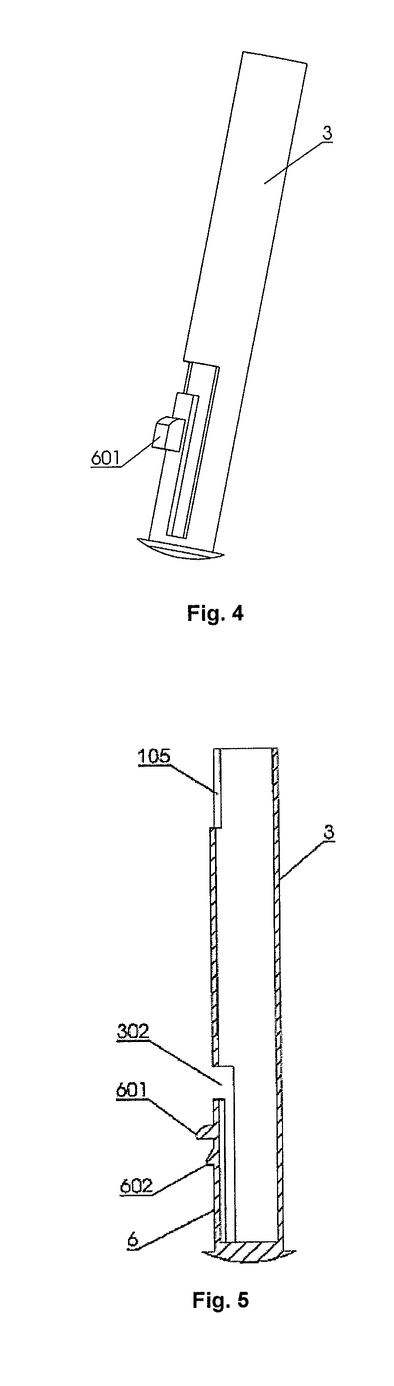
[0090]As shown in FIGS. 2, 3, 4 and 17, the barrel type plunger for use with the needle-retractable safety syringe according to the present embodiment is substantially the same as that of embodiment 1. The differences between the embodiments 3 and 1 lie in that, in the present embodiment, there only is one window 101 provided on the wall of the barrel 1 and one opening 302 provided on the wall of the barrel-like supporting member 3, respectively, and there also only is one flexible rib 6. In addition, only a first projection is provided on the flexible rib 6.
[0091]The supporting member 3 is in a shape of a barrel body having an opened front end and a closed rear end. On the wall of the rear portion of the barrel body, an opening 302 is disposed. A flexible rib 6 extending forwardly along the axial direction of said barrel body is formed on the rear inner wall of the opening 302. On the outer wall of the flexible rib (6), a first projection 601 is formed in a shape of a block body. A...
PUM
 Abstract
Description
Claims
Application Information
 - Generate Ideas
- Intellectual Property
- Life Sciences
- Materials
- Tech Scout
- Unparalleled Data Quality
- Higher Quality Content
- 60% Fewer Hallucinations
Browse by: Latest US Patents, China's latest patents, Technical Efficacy Thesaurus, Application Domain, Technology Topic, Popular Technical Reports.
© 2025 PatSnap. All rights reserved.Legal|Privacy policy|Modern Slavery Act Transparency Statement|Sitemap|About US| Contact US: help@patsnap.com