Magnetic pole position estimation method for ac synchronous motor

Active Publication Date: 2010-11-11
MITSUBISHI ELECTRIC CORP
View PDF2 Cites 11 Cited by
  • Summary
  • Abstract
  • Description
  • Claims
  • Application Information

AI Technical Summary

Benefits of technology

[0015]A magnetic pole position estimation method according to the present invention controls a relative position or relative speed of a motor mover by inputting into a position/speed control unit a value sensed by a motor sensor, performs coordinate transformation, in the use of a pole-error estimation value that the position/speed control unit outputs, of phases of currents or voltages applied to the motor, and estimates a motor magnetic pole position being a relative position of the motor mover by making the pole-error estimation value approximate a true pole-error value that is the difference between a motor magnetic pole position being a relative position of the motor mover and a target magnetic pole position being a target relative position of the motor mover. The estimation method further includes a first pole-error inputting step of inputting a first pole-error estimation value whose phase is shifted by +α from a reference phase; a forward movement step of making the pole-error estimation value approximate the true pole-error value, in the use of a value sensed by the motor sensor when the relative position of the motor mover is moved forward by the first pole-error inputting step; a first phase movement storing step of storing a first pole-error-estimate convergence value that is a phase when relative movement of the motor mover has converged in the forward movement

Problems solved by technology

When an initial magnetic pole position is sensed inaccurately, an axis error phenomenon occurs in which a true magnetic pole position of a motor does not coincide with a magnetic pole position sensed by a control system.
When an absolute encoder is used, it is not required to sense the initial magnetic pole position; however, installation errors or the like will cause the axis error phenomenon.
The axis error phenomenon results in deterioration of accuracy in controlling torques, reduction of the maximum torque to be generated and the like.
However, when there exist disturbances, or especially when there exists large static friction, a torque for estimating magnetic pole position is hidden in the friction torque; therefore, a problem is that a large error remains in its estimation.
To solve this problem, the technique proposes that the amplitude of the signal for the magnetic pole position detection is made larger so that the estimation error is reduced; however, the proposed technique leads to other problems such as larger movements of the motor mover and louder noises during the estimation.
Furthermore, amplifier capacity limits the amplitude of the current; there is accordingly a limit in the technique that the amplitude of the signal for the magnetic pole position detection is made larger in order to reduce its estimation error, which may not solve the problem.
Calculations of the magnetic pole position are performed using sensed values each obtained after the phase of the current for detection is shifted to the reference phase −90 degrees and to the reference phase +90 degrees, which can reduce accuracy degradation caused by static friction in sensing the magnetic pole position.
However, there remain problems below.
Firstly, the technique uses a procedure in which a current with a phase is applied only during an appropriately short time and immediately after that the phase is shifted wi

Method used


Image

  • Magnetic pole position estimation method for ac synchronous motor
  • Magnetic pole position estimation method for ac synchronous motor
  • Magnetic pole position estimation method for ac synchronous motor

Examples


Example

Embodiment 1

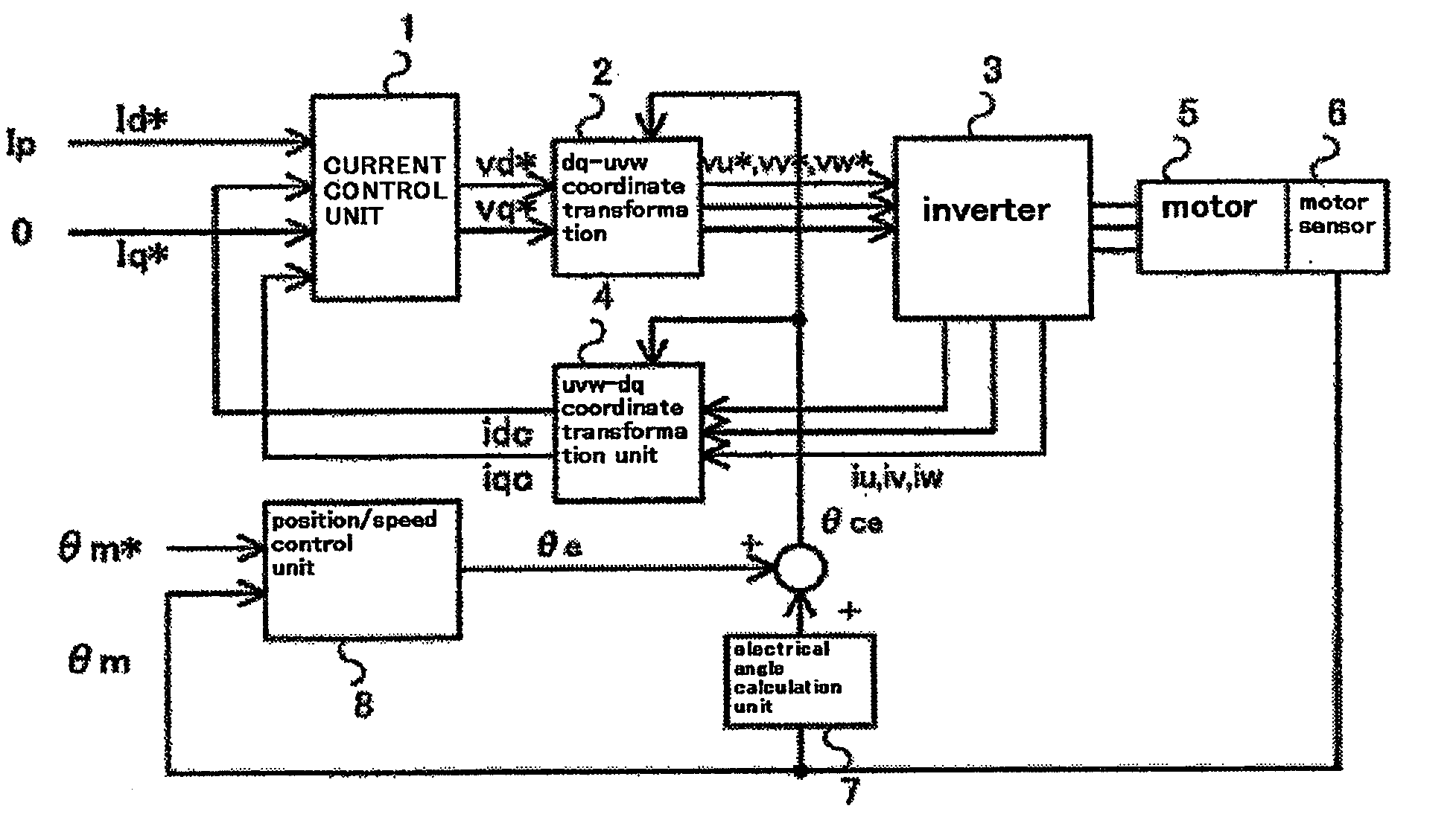
[0042]A configuration of a magnetic pole position estimation device for an AC synchronous motor according to the present embodiment will be explained. In FIG. 1, a configurational diagram of control blocks to control a magnetic pole position according to the present embodiment is illustrated. Hereinafter, such words as “a relative position of a motor mover”, “relative movement of a motor mover” and “a relative speed of a motor mover” are abbreviated to “a motor position”, “motor movement”, and “a motor speed”, respectively. In addition, “a magnetic pole position” and “a motor magnetic pole position” mean that when a magnetic pole of a motor is configured on a motor mover it is a relative position of the magnetic pole with respect to a reference, and that when one or a plurality of pairs of magnetic poles is configured on a motor stator it is a relative position (equivalent to an electric angle) of the motor mover with respect to a pair of magnetic poles.

[0043]A current c...

Example

Embodiment 2

[0074]FIG. 5 illustrates a configurational diagram of control blocks to estimate a magnetic pole position according to the present embodiment. In FIG. 5, the components identical with those in FIG. 1 are referred to as the same numerals in order to omit those explanations.

[0075]In Embodiment 1, the adopted method for generating disturbance torque—error torque—is that a fixed current signal for estimation is applied as a d-axis current in order to shift the pole-error estimation value from that corresponding to the true magnetic pole position; however, in the present embodiment, an adopted method is to apply a signal for estimation whose phase is shifted from the d-axis in a state with no pole error (in a state in which a true magnetic pole position coincides with a target magnetic pole position). More specifically, as shown in FIG. 5, an applied-signal coordinate transformation unit 9 generates dq-axis current command values. In addition, when an application phase θp use...

Example

Embodiment 3

[0078]FIG. 6 illustrates a configurational diagram of control blocks to estimate a magnetic pole position according to the present embodiment. In FIG. 6, the components identical with those in FIG. 1 are referred to as the same numerals to omit those explanations.

[0079]A configuration employed in Embodiment 3 differs from that of Embodiment 1 as follows: in order to generate a magnetic pole error, a method in which the pole-error estimation value is changed from that corresponding to a true magnetic pole position is not adopted, but a method in which the estimation-use signal whose phase is shifted from the d-axis with no magnetic pole error is applied, is adopted—an applied-signal coordinate transformation unit 9 generates a command value for dq-axis currents; and an output from a position / speed control unit 8 is not added to a motor electric angle, but is used as a coordinate transformation position for an applied-signal coordinate transformation unit 9. In comparison ...


PUM


Abstract

If there is static friction, the magnetic pole position estimation is completed at the time when error torque used for magnetic pole position estimation becomes less than the friction, so that there remains magnetic pole error. A problem has been that when the error torque becomes less than a forward static friction, there remains a positive magnetic pole deviation and when the error torque becomes less than a backward static friction, there remains a negative magnetic pole deviation. By shifting in the negative direction and the positive direction initial values for estimating a magnetic pole error in operation sets, a true pole-error estimation value is estimated in the use of a pole-error estimation value having a positive magnetic pole error obtained by the positive shift operation and a negative one obtained by the negative shift operation, which can reduce estimation error due to the static friction.

Description

TECHNICAL FIELD[0001]The present invention relates to sensing a magnetic pole position of AC synchronous motors including linear motors.BACKGROUND ART[0002]In controlling an AC synchronous motor with a servocontrol, the so-called vector control is generally used, in which electric current is resolved into a d-axis component—a current in the direction of a motor flux, and a q-axis component—a current in a torque direction orthogonal to the d-axis, whereby each of the current components is controlled. In order to perform the vector control, it is necessary to precisely sense a position of the magnetic pole.[0003]Linear motors are often used combined with incremental encoders; however, an incremental encoder only senses relative positions, so that it is necessary to sense an initial position of the magnetic pole. When an initial magnetic pole position is sensed inaccurately, an axis error phenomenon occurs in which a true magnetic pole position of a motor does not coincide with a magne...

Claims


Application Information

Patent Timeline
IPC IPC(8): G06F19/00H02P27/04H02P6/06H02P6/08H02P6/16H02P6/17H02P6/28H02P21/00H02P21/22H02P23/16
CPCH02P21/0039H02P21/0035H02P21/146H02P21/18H02P21/22H02P21/24
Inventor TERADA, KEIAOKI, SATOSHI
Owner MITSUBISHI ELECTRIC CORP
Why Eureka
Try Eureka